Sugar + Ascorbic acid 03

Images made through a microscope. All subject types.

Moderators: rjlittlefield, ChrisR, Chris S., Pau

Sumguy01
Posts: 1715
Joined: Mon Jan 28, 2013 11:05 pm
Location: Ketchikan Alaska USA

Sugar + Ascorbic acid 03

Post by Sumguy01 »

Sugar and Ascorbic acid. Same slide and same set up as last two sets.
My first try with Zerene stereo pair.
Image
Image

Saul
Posts: 1783
Joined: Mon Jan 31, 2011 11:59 am
Location: Naperville, IL USA
Contact:

Post by Saul »

Very nice 3d look even on the single photo !
What technique was used ?

rjlittlefield
Site Admin
Posts: 23608
Joined: Tue Aug 01, 2006 8:34 am
Location: Richland, Washington State, USA
Contact:

Post by rjlittlefield »

I really like the single image.

But the stereo pair looks weird to me. There are lots of differences between the two views that appear unrelated to depth. It hurts my head to keep them fused.
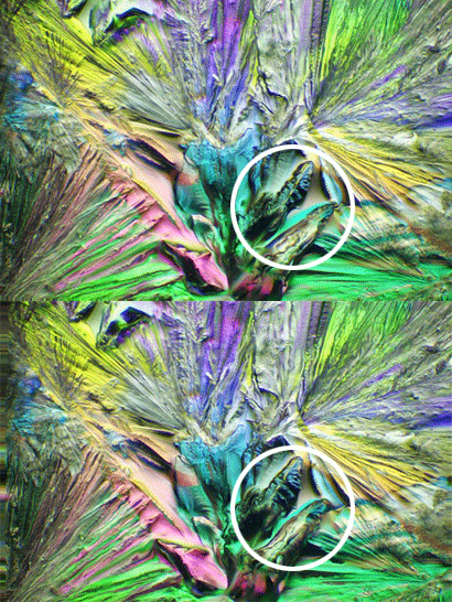
What stacking method did you use?

--Rik

Pau
Site Admin
Posts: 6065
Joined: Wed Jan 20, 2010 8:57 am
Location: Valencia, Spain

Post by Pau »

rjlittlefield wrote: But the stereo pair looks weird to me. There are lots of differences between the two views that appear unrelated to depth. It hurts my head to keep them fused.
Well, I think that the relief look at the first image is not due to differences in height but to differences in refraction index with the direction (typical of anisotropic crystals) that show under cross polarizers as both interference colors and differences of light intensity (no actual shadows)

This would not match the synthetic stereo relief interpretation, so a mismatched and weird look is not surprising.
Pau

rjlittlefield
Site Admin
Posts: 23608
Joined: Tue Aug 01, 2006 8:34 am
Location: Richland, Washington State, USA
Contact:

Post by rjlittlefield »

Let me explain more about what I mean by "weird".

Here is a two-frame animation that alternates left and right views.

Image

With normal well formed stereo, display like this looks like an object that rocks left/right/left/right, with matching features moving just side-to-side and looking very much the same in both views.

But in this one, the rocking looks more like upper-left to lower-right, tipped almost 30 degrees off horizontal. This might be caused by specifying both X- and Y-shifts during stereo generation, or possibly by rotating the images after generation.

In addition the two "pillars" or "ridges" inside the white circle change appearance dramatically between one view and the next.

I think it's the combination of the tipped axis and the dramatic change in appearance of the pillars/ridges that I'm reacting to. Given the tilt, it's hard for me to tell for sure about the rest.

Sumguy01, let me know if you'd prefer this post split off to a technical discussion. I don't want to detract from your images.

--Rik

Sumguy01
Posts: 1715
Joined: Mon Jan 28, 2013 11:05 pm
Location: Ketchikan Alaska USA

Post by Sumguy01 »

Hi Guys.
Thanks for the comments.
This image is 10x obj. Polarized, oblique with quarts wedge retarder.
Zerene stack 37 images.
The stereo pair is also Zerene. Its my first try with stereo pairs.
Constructive criticism is always welcome.
To me the stereo pair looks great but I would like to try it again if Rik has suggestions.
The settings I used for the stereo pairs.
output images = 3
shift x = -3, 3
shift y = -2, 2 ( ?? not for sure about this one)
stack = Dmap
Rik we can continue this wherever you think its appropriate. It makes no difference to me.

rjlittlefield
Site Admin
Posts: 23608
Joined: Tue Aug 01, 2006 8:34 am
Location: Richland, Washington State, USA
Contact:

Post by rjlittlefield »

Sumguy01 wrote:The settings I used for the stereo pairs.
output images = 3
shift x = -3, 3
shift y = -2, 2 ( ?? not for sure about this one)
stack = Dmap
The major problem is shift y. For simple stereo pairs you should always use just shift x. Shift y is only for special cases that would be a distraction here. Set shift y = 0% .

Usually I use PMax for stereo pairs, because it's not so likely to do strange things with front/back overlaps. DMap stereo works well with simple geometry that has no overlaps, but I'll usually run PMax first and then move on to DMap only if the PMax did something I don't like.

+-3% in X may be too much, given the shallow depth of the stack. On the other hand, with flattish crystals it's usually helpful to have some depth exaggeration.

The tension between these two aspects makes it difficult for me to choose best separation beforehand.

What I usually do in such cases is pick a couple of limits that I think are probably too large, then generate more than 3 images, walk away, and come back after the computer is finished, to choose the separation that I like best. In your case, +-3% and 7 frames would allow you to evaluate 1%, 2%, 3%, and so on up to 6% total offset by previewing appropriate pairs. The center output against one on either side is 1%, the two on either side of center are 2% total (+-1%), 3% total is -2% and +1%, and so on. Sometimes I'll decide that say 3% total is not enough but 4% looks like too much, and then I'll render again at 3.5% total, specified as 2 frames at +-1.75% .

I hope this helps -- looking forward to another iteration!

--Rik

Sumguy01
Posts: 1715
Joined: Mon Jan 28, 2013 11:05 pm
Location: Ketchikan Alaska USA

Post by Sumguy01 »

Rik
Thanks for the helpful information.
Does this look better to you?
Image

rjlittlefield
Site Admin
Posts: 23608
Joined: Tue Aug 01, 2006 8:34 am
Location: Richland, Washington State, USA
Contact:

Post by rjlittlefield »

Sumguy01 wrote:Does this look better to you?
Lovely! Very pleasant and easy to look at. The geometry now makes perfect sense. Well done!

--Rik

Post Reply Previous topicNext topic