Finally built my dream focus stacking setup

Have questions about the equipment used for macro- or micro- photography? Post those questions in this forum.

Moderators: rjlittlefield, ChrisR, Chris S., Pau

rjlittlefield
Site Admin
Posts: 23625
Joined: Tue Aug 01, 2006 8:34 am
Location: Richland, Washington State, USA
Contact:

Post by rjlittlefield »

I am truly surprised that I do not see any shifts, neither translational nor rotational.
...
Not sure if Zerene Stacker has matrix logged in log view to verify this
The console log does contains alignment information, as shift, rotate, scale numbers.

Your image, reproduced here from the previous page:
Image
Though the image is not as pretty, but it illustrates how good the setup is.
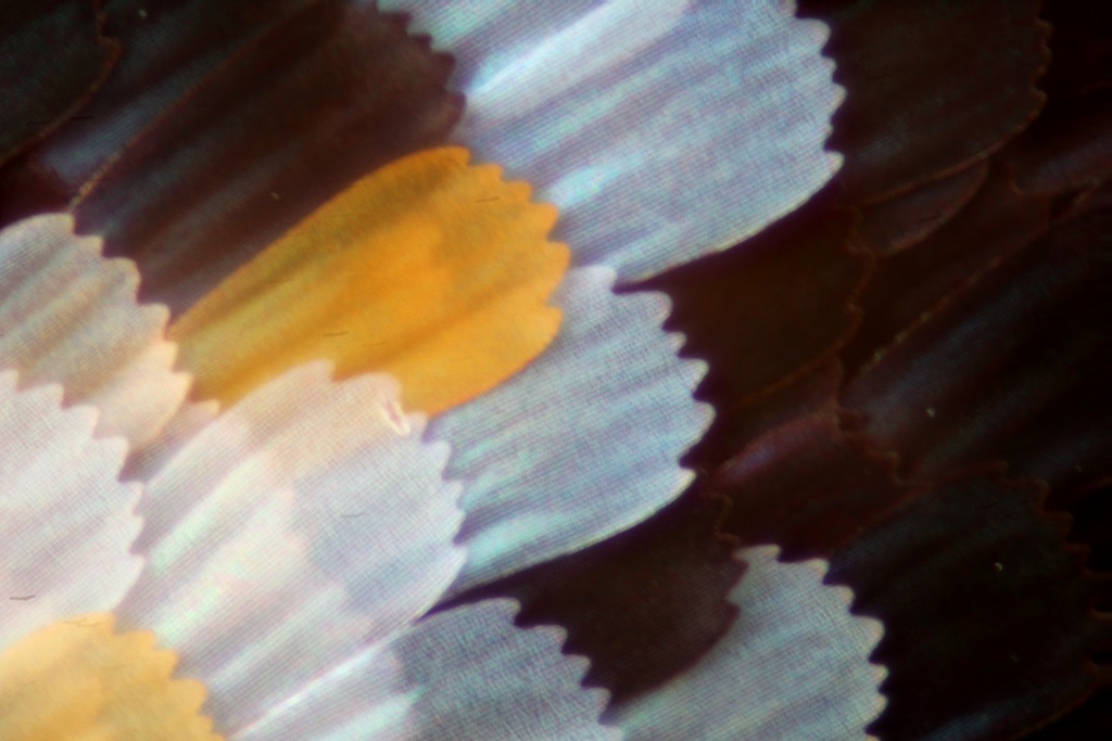
With respect, I disagree. This image looks awful. If this were actual pixels, not the whole frame resized, then I would say that it appears to be motion blurred. But being the whole frame, I'll say that it appears to be severely motion blurred.

If you have alignment turned off in the software, then this could be due to slight frame-to-frame shifts being combined by PMax.

But if you still have alignment turned on (as suggested by asking about the matrix, plus the apparent dust trails in the image), then I think the problem must be vibration causing blur in the individual frames.

If the problem is not vibration, then perhaps this objective has been damaged by dropping. If the objective is really this bad, it should be returned as obviously defective.
just realized something, it is an 50X objective with NA of 0.45, meaning effective aperture is f/49!!! Diffraction is killing the sharpness
I calculate even smaller, f/56 (=50/(2*0.45). But you're giving diffraction too much power here. f/56 will certainly be very blurred at actual pixels, but with the full frame scaled to web size, the image should again look sharp. Many excellent images have been posted using that same model of objective.

--Rik

mjkzz
Posts: 1693
Joined: Wed Jul 01, 2015 3:38 pm
Location: California/Shenzhen
Contact:

Post by mjkzz »

Thanks Rik

I will check the log.

For effective aperture, I used a calculator from Extreme Macro website by Johan. I think it uses some sort of tan of asin stuff. Here is the link:

http://extreme-macro.co.uk/microscope-o ... calculator

That image is a resize of WHOLE frame, even resized, it still looks fuzzy. It could be that it was so cheap that it might be damaged. It looks like so even in view finder for each frame. I even tried to use continuous light with everything locked up tight, it still looks fuzzy. It costs about 190USD, so could be a damaged one.

Yeah, you are right about turning on the alignment (it was on). But I have final images looking weird even with alignment on. Anyways, here is an image with all alignment options turned OFF.

Image

Just in case I am not using Zerene correctly, this is the setting for above image

Image

rjlittlefield
Site Admin
Posts: 23625
Joined: Tue Aug 01, 2006 8:34 am
Location: Richland, Washington State, USA
Contact:

Post by rjlittlefield »

Yes, all checkboxes clear are the proper settings to turn alignment off.

The image with alignment on is clearly better, much less bright halo where the ends of the bright scales overlap the dark scales. But rendering of fine detail is not much different, and the dust trails appear uniform, not jagged. This combination suggests that there is general side-to-side movement from front to back of the stack, but not much frame-to-frame jitter.

The formula that I gave for effective aperture is correct. I haven't looked at Johan's calculator, but in general calculators that use tan of asin are usually based on an incorrect belief that the principal planes are really planes. They're not, as discussed at http://www.photomacrography.net/forum/v ... 511#196511.

--Rik

mjkzz
Posts: 1693
Joined: Wed Jul 01, 2015 3:38 pm
Location: California/Shenzhen
Contact:

Post by mjkzz »

OK, I have been using Zerene by habit lately and forgot my own, so I tried with my stacking software which produces edges when there are shifts between frames, here are the results: first is normal order, second is reverse order. It is obvious that there are shifts but I do not think it is killing it.

Image

Image

mjkzz
Posts: 1693
Joined: Wed Jul 01, 2015 3:38 pm
Location: California/Shenzhen
Contact:

Post by mjkzz »

rjlittlefield wrote:This combination suggests that there is general side-to-side movement from front to back of the stack, but not much frame-to-frame jitter.
Ah, maybe my camera/lens is not positioned correctly, it is forming an angle with moving axis!! Gotta fix that.

Thanks for the right formula.

johan
Posts: 1005
Joined: Tue Sep 06, 2011 7:39 am
Contact:

Post by johan »

Corrected, thank you
My extreme-macro.co.uk site, a learning site. Your comments and input there would be gratefully appreciated.

mjkzz
Posts: 1693
Joined: Wed Jul 01, 2015 3:38 pm
Location: California/Shenzhen
Contact:

Post by mjkzz »

It turns out to be pretty hard to make sure camera/lens axis is parallel with moving axis. Tried to use a laser mounted in hotshoe of camera, but then what if the laser is not aligned correctly? That will defeat the effort.

Also tried to shine laser through the lens via view finder, still not good enough, I wish there is a reference point on the camera . . . see right now the camera is mounted via its tripod thread which is a single point.

Any ideas? Thanks.

rjlittlefield
Site Admin
Posts: 23625
Joined: Tue Aug 01, 2006 8:34 am
Location: Richland, Washington State, USA
Contact:

Post by rjlittlefield »

mjkzz wrote:Any ideas? Thanks.
I've seen people talk about using an Arca-Swiss plate with a lip to mate with the camera back.

However, I can't make the numbers work out so as to pin blame on the camera being mounted off-axis. Here's the problem...

If I'm reading correctly, you did 99 steps at 0.3125 microns per step. That makes a total depth of 99*0.3125/1000 = 0.030938 mm. Then, in the image, you have 50X onto an APS-C sensor, which means frame width about 22/50 = 0.44 mm. In the image as posted, I see that the dust trails are about 2.3% of frame width, which would mean 0.44*2.3% = 0.01012 mm shift on subject.

If the problem were due to the camera being mounted off-axis, then it would have to be pointed at such an extreme angle as to move 0.01 mm sideways in only 0.03 mm of forward motion. I think you'll agree that alignment off by 1 part in 3 would be easily visible by eye.

Either I've completely blown the math, or something else is going on.

--Rik

mjkzz
Posts: 1693
Joined: Wed Jul 01, 2015 3:38 pm
Location: California/Shenzhen
Contact:

Post by mjkzz »

Hi Rik, 100% agree

I was along the same path as you did, I zoomed up my stacking result and lined edges pointed by the red arrow has 127 pixels of width, suggesting there is about 2.45% (127 / 5184) translational shift, same as the dust trail suggests (I kind of like the alignment algorithm)

I think camera being off axis is OK as long as axis of lens is parallel with moving axis. But if the axis of lens is forming an angle with moving axis IS problematic.

But yeah, atan(1/3) ~ 18.4 degrees, I am sure I can spot that, I am pretty sure the step size is 0.3125um, so something else is going on. Will see.

mjkzz
Posts: 1693
Joined: Wed Jul 01, 2015 3:38 pm
Location: California/Shenzhen
Contact:

Post by mjkzz »

It is definitely moving at 0.3125um, just tested, had a digital micronmeter hooked to the rail (loosely), move it 1698.3125um as displayed on my Android phone, the actual reading is 1.66mm, so the discrepancy is about 2.2%, this could be due to not placing the meter right or maybe just plain error.

So there is nothing wrong with step size part, and from practical point of view, it is necessary to step at 1/32 micro step mode to reduce vibration, I even slow it down further, pulsing step motor at 500hz (vs 2000hz for other modes)

So what happened to the result and the 18.4 degrees angle . . .? Will see

elf
Posts: 1416
Joined: Sun Nov 18, 2007 12:10 pm

Post by elf »

Can you measure whether or not the camera is tracking straight by measuring along the side of one of the extension tubes with your digital micrometer while doing a stack?

mjkzz
Posts: 1693
Joined: Wed Jul 01, 2015 3:38 pm
Location: California/Shenzhen
Contact:

Post by mjkzz »

OK, here is a video showing that there is an angle between lens and moving axis. But it is probably less than 1 degree, I did adjust it a bit afterward, but not by much. Unfortunately, I returned the objective, else I will try it again.

https://youtu.be/Azmo7BLiNGM

One thought is, since there are about 10um displacement from image alignment (dust trail or edge width), and it seems uniform across 99 images, it means there are 10/99 = 0.101um displacement between images, that is 101nm or 1/5th of average wavelengths of visible light. could it be other factors involved?

Until I get another 50x and repeat this, I do not know what is going on.

rjlittlefield
Site Admin
Posts: 23625
Joined: Tue Aug 01, 2006 8:34 am
Location: Richland, Washington State, USA
Contact:

Post by rjlittlefield »

mjkzz wrote:I do not know what is going on.
My guess -- only a guess -- is that as you turn the screw to advance the carriage, the carriage is twisting every so slightly with respect to the support rails. In your setup, it appears there could be 100 mm or so from the center of the carriage to the plane of the subject. Given this long lever arm, it does not take much rotation of the carriage to produce the observed amount of shift of the lens across the subject. With this mechanism, you're looking at a total carriage twist of only asin(10um/100mm) = asin(0.010/100) = 0.0057 degrees.

To reduce such problems, try adding some elastic bands as shown by mawyatt at http://www.photomacrography.net/forum/v ... 962#199962 . That will keep the carriage locked against one limit of its rotation as it moves forward or backward.

--Rik

mawyatt
Posts: 2497
Joined: Thu Aug 22, 2013 6:54 pm
Location: Clearwater, Florida

Post by mawyatt »

Peter,

Here's a link to a rail that Smokedaddy found, it's too long for my setup but you might find it useful. Has 1mm pitch.

Best,

Mike


http://www.ebay.com/itm/PBC-Linear-Moto ... SwNSxU721S

mjkzz
Posts: 1693
Joined: Wed Jul 01, 2015 3:38 pm
Location: California/Shenzhen
Contact:

Post by mjkzz »

Hi Mike,

I am not sure about it because I have never used that kind of rail. I am truly impressed with what I got. I now have 3 of that rail (not counting the one I had already), these are solid enough to build my next projects as a prototype for proof of concept.

Some day, I will post pictures of all the rails I have tested before building my own. Those rails look solid, but they are not suitable at all.

Post Reply Previous topicNext topic