How NOT to repair a microscope power supply...

Have questions about the equipment used for macro- or micro- photography? Post those questions in this forum.

Moderators: rjlittlefield, ChrisR, Chris S., Pau

rjlittlefield
Site Admin
Posts: 23608
Joined: Tue Aug 01, 2006 8:34 am
Location: Richland, Washington State, USA
Contact:

How NOT to repair a microscope power supply...

Post by rjlittlefield »

This is an autopsy report regarding a microscope body that I bought on eBay several years ago.

It was an Olympus CH, and mostly I wanted it for the focusing mechanism. The eBay ad said that the light didn't work. When the scope came it was clear that the base had experienced some sort of trauma, because all the mounting lugs had been broken off the baseplate and the thing was held together with orange plastic tape. Nonetheless the focusing mechanism worked fine and the condenser and objective turret were in good shape. Oddly, the light also worked fine. I figured the auction place just didn't know to work the brightness slider along with flipping the power switch.

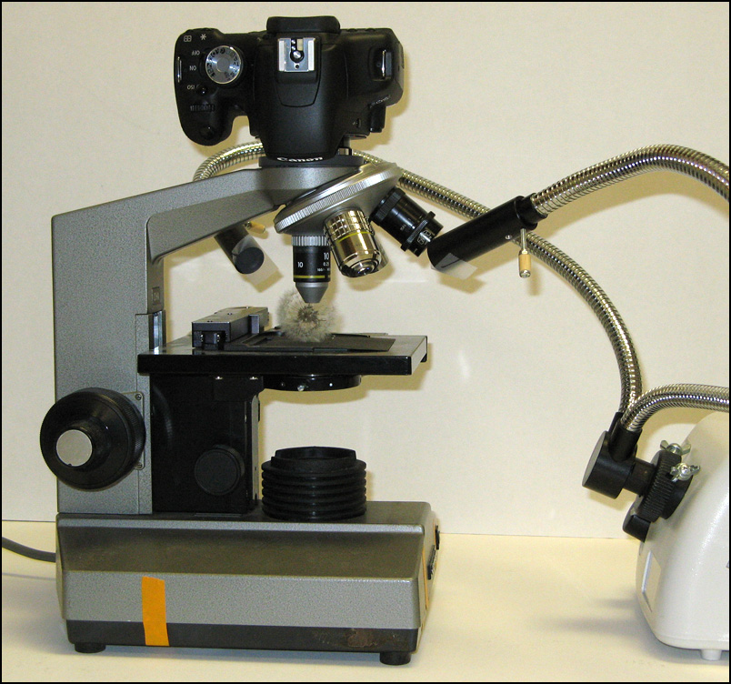
Anyway, I've been using the scope for several years for a variety of purposes, for example as shown here in my Bellows on scope base thread from clear back in 2010.

Image

Until recently, I never got around to taking the baseplate off.

When I finally did, this is what I saw:

Image

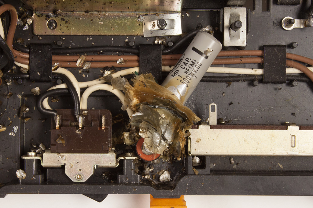
OK, fine, so an electrolytic capacitor exploded. They fail that way once in a while, though in my experience it's pretty rare.

On closer consideration, though, I noticed something rather odd. This particular electrolytic capacitor, 0.1 microfarad at 500 WVDC, seems to have been wired essentially straight across the AC mains. Of course that's a recipe for disaster, since DC electrolytic capacitors tend to turn into short circuits if they're ever subjected to reversed voltage.

So now I have this vision of a botched repair, in which some slightly distracted repair person grabs the wrong type of capacitor to replace a failed one, solders it in, puts the scope back together, turns it on, and very shortly afterward experiences something rather like a firecracker going off inside the scope. "Hello, eBay? I have something to sell..."

But it's just a vision, and sometimes imagination fails me. Perhaps some other component has failed too, causing AC to be present in a place where there is supposed to be only DC.

For what it's worth, here's the overview. The base is just labeled CH, with serial number 309978; the arm says CHA.

Image

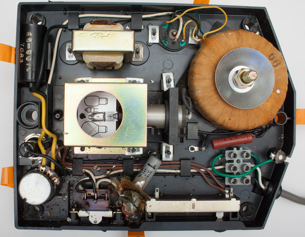
Can somebody with a working scope tell me what sort of component is supposed to be in that position, and maybe provide a schematic?

--Rik

g4lab
Posts: 1437
Joined: Fri May 23, 2008 11:07 am

Post by g4lab »

The .1mfd 500 volt capacitor looks to have one lead connected to the chassis which should be electrically continuous with the green ground lead and corresponding pin on the AC plug.

Probably the cap that blew and the 0.1 are part of a scheme to keep electrical noise spikes from exiting the unit into the AC line. The scope probably has some kind of SCR or triac to control the lamp brightness and when these are dimming (ie. chopping the AC duty cycle with very sharp rise times, they can put out a lot of buzzing noises that can be picked up by other electronic gear. So companies that want to be good citizens put filtration at the input which prevents such sharp rising transients from going either into or out of the piece of equipment. Maybe lightning struck in the neighborhood and popped that capacitor. If it is just a line filter that would explain it still working properly. It appears to be connected between the white wire (neutral) and chasis ground (green). In order to make a high voltage AC resisting capacitor they may have taken two capacitors and wired them in series with the "outer foils" opposite. If they were both identical 500 volt DC caps that should have been close since
the peak voltage to resist in a 120 volt AC (rms) circuit is about 170 or 180 volts. So two 500 volt caps should have done fine.
But when lightning strikes all bets are off. dV/dT and dI/dT go into other regimes and things pop.

wjy is there both a brightness slider and also apparently a variable resistor/potentiometer at the rear. It also has two transformer and coil looking things. The big toroidal at the front and the cheap looking one on the side. If they only have two terminals they one of them is probably an inductor to reduce the rate of rise on the power phase control. Often these things have SCR/triacs driving the step down transformer which then sort of converts the waveform back towards a sine wave because of inductive reactance.

rjlittlefield
Site Admin
Posts: 23608
Joined: Tue Aug 01, 2006 8:34 am
Location: Richland, Washington State, USA
Contact:

Post by rjlittlefield »

Sorry, the photo is not clear.

The cap that blew and the gray label you can still read are the same cap. There were definitely not two, back to back. As for the wiring, my meter shows around 1 ohm from one end to the neutral pin of the plug, 1 ohm from the other end to the hot pin of the plug, and infinity from each end to chassis / ground pin. What looks like a connection to chassis is just mechanical mounting to a plastic post on a plastic baseplate. I like the idea that it's a filtering cap, but DC makes no sense in this position.

According to the operating manual, the flat adjustable thing at upper center is a "Line voltage selector switch." It's labeled on the outside as 100V-110V-120V. The adjustable pot at lower left is described as a "Rheostat trimmer screw // After switching on, if necessary, rotate this screw with a coin until the bulb is dimly lit, with the sliding control switch at minimum voltage position." Text on page 7 says that "The built-in rheostat incorporates a thyristor in its semi-conductor circuit", so that's certainly consistent with the idea of filtering noise.

The black cylinder with gold lettering has 4 wires coming out of it: two yellow, two black. The two yellow wires go to the rheostat trimmer, which is paralleled by the main brightness slider. I'm guessing that the thyristor is located inside that black cylinder, since I can't see where else it would be.

--Rik

g4lab
Posts: 1437
Joined: Fri May 23, 2008 11:07 am

Post by g4lab »

The cap that blew and the gray label you can still read are the same cap. There were definitely not two, back to back. As for the wiring, my meter shows around 1 ohm from one end to the neutral pin of the plug, 1 ohm from the other end to the hot pin of the plug, and infinity from each end to chassis / ground pin. What looks like a connection to chassis is just mechanical mounting to a plastic post on a plastic baseplate. I like the idea that it's a filtering cap, but DC makes no sense in this position.
If it is not grounded and one of two it could be that the engineers erroneously decided a 500 WV cap would be OK but it did not turn out that way. I would say excise the old cap since it is blown up anyway and lets have a look at whatever loose connections are floating in the air.
In the mean time I will look and see if I can find you a suitable replacement candidate online.

http://www.mouser.com/ProductDetail/Vis ... hAOg%3d%3d

https://www.surplussales.com/Capacitors ... icC-2.html
According to the operating manual, the flat adjustable thing at upper center is a "Line voltage selector switch." It's labeled on the outside as 100V-110V-120V. The adjustable pot at lower left is described as a "Rheostat trimmer screw // After switching on, if necessary, rotate this screw with a coin until the bulb is dimly lit, with the sliding control switch at minimum voltage position." Text on page 7 says that "The built-in rheostat incorporates a thyristor in its semi-conductor circuit", so that's certainly consistent with the idea of filtering noise.
Now that you mention it, one often does see these trimmers. They help move the operating point of the SCR circuitry, probably to help cope with conditions of differing line voltage and frequency. I have a recollection of twiddling one and having do nothing at all but I can't remember on what piece of gear that was. Possibly some fiber optic illuminator which also frequently will have an SCR dimmer driving a step down transformer.

The black cylinder with gold lettering has 4 wires coming out of it: two yellow, two black. The two yellow wires go to the rheostat trimmer, which is paralleled by the main brightness slider. I'm guessing that the thyristor is located inside that black cylinder, since I can't see where else it would be.
I agree and that was my thought too because the wires lead from the adjustment pot and to the transformer.

mpan
Posts: 46
Joined: Mon Sep 14, 2015 4:20 pm

same problem

Post by mpan »

Hello, I've had the same thing happen to my scopes in less than a week. I'm hoping it's due to age. Any suggestions on which of these capacitors would be the better choice or should I be looking for something else?

Image
Image
Mike

mawyatt
Posts: 2497
Joined: Thu Aug 22, 2013 6:54 pm
Location: Clearwater, Florida

Post by mawyatt »

Mike,

I have no experience with this scope so take this with a grain of salt!! That's a really old cap, and today you can use a good axial lead plastic 0.1uF at least 500V cap in it's place. There's no need to replace it with the "exact" type construction cap, just a equivalent "electrical" cap, and no need to pay that price!! The equivalent cap shouldn't cost more than $1 I would think!

Hope this helps,

Best,

Mike

Edit: Here's a cap that should work fine, although it's not axial. Just keep the lead to the hot AC line shortest.

https://www.ebay.com/itm/10pcs-CBB-104J ... u&LH_BIN=1
Research is like a treasure hunt, you don't know where to look or what you'll find!
~Mike

mpan
Posts: 46
Joined: Mon Sep 14, 2015 4:20 pm

Post by mpan »

Thank you for your help.
Mike

normandy
Posts: 5
Joined: Wed Feb 09, 2011 10:55 am

Olympus CHA image of base electronics

Post by normandy »

I have a CHA and will remove the base tomorrow and click some pics of the internal workings for you. Is that all you need ?

mpan
Posts: 46
Joined: Mon Sep 14, 2015 4:20 pm

Post by mpan »

I've acquired several capacitors from a friend. I installed them yesterday and the scopes are working again! Thanks again for yall's help.
Mike

DavyC
Posts: 109
Joined: Sat Sep 22, 2018 1:53 pm
Location: UK

Post by DavyC »

An old thread, but it should be worth noting. The AC mains voltage of some countries outside the US can be 240V. Components should be suitably rated. In this microscope the capacitor was connected across the ac mains as a filter. The DC rating is generally taken as approx 2.5 times the AC rating. Better though here to spec component in its AC mains rating. If you can physically fit a higher AC voltage rated capacitor, so much the better. On the component capacitance value of 0.1 uf. You could use a higher value of up to around 0.47 uf. Its not critical. I would use a Polypropylene metallized film type capacitor. Available in high voltage and to a degree self healing.

ChrisR
Site Admin
Posts: 8671
Joined: Sat Mar 14, 2009 3:58 am
Location: Near London, UK

Post by ChrisR »

Yes - If they're directly on the mains line these should be X or Y rated - as above, much higher rated. Plenty of info online - eg https://electronics.stackexchange.com/q ... tly/333049
Chris R

Post Reply Previous topicNext topic