DIY Fluorescence with Zeiss fluoro condenser - help needed

Have questions about the equipment used for macro- or micro- photography? Post those questions in this forum.

Moderators: rjlittlefield, ChrisR, Chris S., Pau

viktor j nilsson
Posts: 423
Joined: Fri Mar 01, 2013 1:43 am
Location: Lund, Sweden

DIY Fluorescence with Zeiss fluoro condenser - help needed

Post by viktor j nilsson »

Image

Quick question. What does the slot screw B do ? The Zeiss Fluoro condenser manual only mentions slot screw A, which focuses the iris. There seems to be a heat absorption filter around there, but it doesn't make sense to focus that, does it?
Last edited by viktor j nilsson on Thu Jun 04, 2020 2:27 am, edited 1 time in total.

Pau
Site Admin
Posts: 6071
Joined: Wed Jan 20, 2010 8:57 am
Location: Valencia, Spain

Post by Pau »

A is not actually a functional screw for this task but for dismounting the diaphragm body (and it contains the spring loaded pin that allows centering it together with the regulating screws).
B locks the diaphragm body position and once unlocked allows to move the diaphragm body longitudinally, you can slide A for it

I also had this doubt because the manual is unclear (or just wrong), quite surprising with Zeiss stuff.

Image

Yes, there is a heat absorption filter (Schott KG01, I think) inside. It can be removed dismounting the rear part of the body containing diaphragm body as I did because it is not necessary with LEDs
Pau

viktor j nilsson
Posts: 423
Joined: Fri Mar 01, 2013 1:43 am
Location: Lund, Sweden

Post by viktor j nilsson »

Image

I'll just add the relevant Figure from the manual to complement the text Pau added.

viktor j nilsson
Posts: 423
Joined: Fri Mar 01, 2013 1:43 am
Location: Lund, Sweden

Post by viktor j nilsson »

Thanks, Pau! That clears up my confusion. The Manual is indeed ambiguous on this subject.

So, to remove the heat-absorption filter I need to loosen both slot screws (A and B in the first picture), unscrew the iris screw (3.8 in the manual) and both centering screws (3.5). Then I just slide out the iris assembly? Is there anything that can come loose in the process that I need to be aware of? Is the spring-loaded pin tricky to get back in place?


I recieved the Fluoro condenser yesterday. Very nice, solid thing. Next step is to adapt it to my Wild M20 that has Nikon CF Fluor objectives. Unfortunately the top telan lens was delaminated around its perimeter, but luckily both the top and bottom lens came off easily so I will probably use it without its optics, using direct projection. The dovetail also came off easily. After having read this old thread, I was worried that that was going to be a problem: https://www.photomacrography.net/forum/ ... 4c4094d639

It came with a filter cube that had FITC and Rhodamine filters. One barrier filter and one dichroic mirror was damaged, but I have a nice set of dichroic filters so I should be able to produce a couple of nice filter sets that will allow for UV, blue and green LED fluorescence.

I don't know if there is a document that shows the transmission characteristics of each filter in the old Zeiss filter sets. But I assume that the general characteristics of FITC and Rhodamine filter sets haven't changed very much, so they should look something similar to this:

FITC:
Image

Rhodamine:
Image

Ichthyophthirius
Posts: 1152
Joined: Thu Mar 07, 2013 5:24 am

Post by Ichthyophthirius »

Hi,

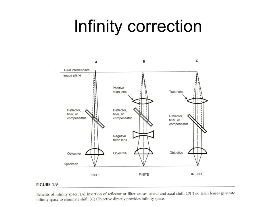
In general, removing the Telan lenses is not a good idea. They create an infinity space inside the epifluorescence condenser. This allows tilted beamsplitters to be used in the lightpath. It will still work but its not ideal. See page 5: http://www.alanwood.net/downloads/olymp ... ochure.pdf

The peripheral delamination in contrast is unlikely to be a problem.

Telan lenses are also great dust protection :wink:

Regards, Ichty

viktor j nilsson
Posts: 423
Joined: Fri Mar 01, 2013 1:43 am
Location: Lund, Sweden

Post by viktor j nilsson »

Aha! I had not thought of that aspect at all. I now also found this slide, which also illustrates it well:

Image

I had only thought of telan lenses as a necessary evil to maintain the correct tube length. I now appreciate them more!

This is what the peripheral delamination looks like:
Image

I'll keep it as it is for now and maybe try to deal with it if or when I start to produce some acceptable fluorescence images. [/img]

Pau
Site Admin
Posts: 6071
Joined: Wed Jan 20, 2010 8:57 am
Location: Valencia, Spain

Post by Pau »

viktor j nilsson wrote:So, to remove the heat-absorption filter I need to loosen both slot screws (A and B in the first picture), unscrew the iris screw (3.8 in the manual) and both centering screws (3.5). Then I just slide out the iris assembly? Is there anything that can come loose in the process that I need to be aware of? Is the spring-loaded pin tricky to get back in place?
No, you don't want to remove the diaphragm but to open the tube by the other side removing the three bolts around it, one of them marked with a blue arrow:

Image

Removing the diaphragm is not difficult, just a bit tricky to return it to its place, I've done it, but if not needed is better to let it in place

Delamination is the plague with Zeiss West stuff. Mine came without delamination but now, few years later, it is partially affected like yours.
I've bought a replacement perfect lens (rare to happen at eBay) A bit of delamination is not terrible but can induce lower contrast.
Ichty is right as he always is, although with my Nikon 210 corrected I use it without telan lenses. I think that Nikon M plans 210 are designed to work without telan, 210=160+50 and its epiilluminator height just measures 50mm (of course with infinites I also do it)
Pau

Pau
Site Admin
Posts: 6071
Joined: Wed Jan 20, 2010 8:57 am
Location: Valencia, Spain

Post by Pau »

There are many papers with info about filters in Zeiss literature, I could send you some of them. Filters have evolved quite a lot from the Zeiss Standard series beginning and much more after its end, are you sure to have the original filter sets?

I also have some surplus filters adequate for this illuminator cubes.
You can contact me by PM
Pau

viktor j nilsson
Posts: 423
Joined: Fri Mar 01, 2013 1:43 am
Location: Lund, Sweden

Post by viktor j nilsson »

Thanks for the offer, Pau! I might take you up on that offer as I get closer to having a working fluorescence setup. I have a couple of things I need to sort out first, the biggest of which is constructing a focusable "lamphouse". I know you used the optics from a HBO lamphouse, but I was planning on using an eyepiece as collector lens and 3D printing a holder similar to your "Custom machined aluminum adapter". Do you know, approximately, the focal length of the optics in your HBO lamphouse? I believe you tried both the HBO50 and HBO100 lamphouses - did the filament magnification change significatnly between these? I am going to try out a couple of different options to see if they produce a sufficiently large illuminated field. The LED dies also varies quite a bit in size, so I don't think that there is going to be a single collector lens that is ideal for all of them.

As I seem to be working from home for the foreseeable future, I can't easily use the 3D printer at work, so I am not sure when or how this will proceed.

Regarding filters, I picked up that €25 set on eBay from a german seller (jenmedgmbh) that contained 7 dichroic filters (17.5mm, fits OK). I've also bought a nice Chroma T400LP long pass filter that I will cut into a 22mm dichroic mirror. Here are the characteristics of these filters:

Image


In addition, at least two of the filters in the Zeiss filter cube looks to be in good order and were clearly labeled so that I know what they are.

One was a 18mm narrow-band excitation filter 545RDF35:
Image

And one a 22mm long-pass dichroic mirror 585ALP:
Image

Both of these were - I assume - from the Rhodamine cube, so it seems like this cube used a 585nm long-pass dichroic mirror - not a short-pass one as in the Nikon graphic I posted above.

viktor j nilsson
Posts: 423
Joined: Fri Mar 01, 2013 1:43 am
Location: Lund, Sweden

Post by viktor j nilsson »

In the other cube (FITC?), the purple dichroic mirror and the green-yellow barrier filter was fried. The excitation filter side, however, looked OK. This side contained two identical stacked filters. They weren't labeled and looked like this:

Image

They look a little too dark-blue to be a 470-500nm filter, don't you think? Does anyone have an educated guess as to what they are?

viktor j nilsson
Posts: 423
Joined: Fri Mar 01, 2013 1:43 am
Location: Lund, Sweden

Post by viktor j nilsson »

Image

Here's an updated version of the filters I currently have.

Edit: I removed one panel from the version I originally posted (the fitc.exc panel). This showed the spectrum from Nikon's FITC excitation filter cube, but as I suspected, the deep-blue filters I had are likely not this filter at all.
Last edited by viktor j nilsson on Thu Jun 04, 2020 1:40 am, edited 1 time in total.

Pau
Site Admin
Posts: 6071
Joined: Wed Jan 20, 2010 8:57 am
Location: Valencia, Spain

Post by Pau »

I believe you tried both the HBO50 and HBO100 lamphouses - did the filament magnification change significatnly between these? I am going to try out a couple of different options to see if they produce a sufficiently large illuminated field. The LED dies also varies quite a bit in size, so I don't think that there is going to be a single collector lens that is ideal for all of them.
Yes, I have two lenses and with most LEDs I have the HBO lamp house lens is much better, the Halogen* 100 lamphouse lens oly works decently with the big Cree XML2 . The HBO lens has much shorter focal length than the Hal.
Maybe the UV transmission could be an issue with eyepieces. Another point to take in account is the built in lens that most LEDs have and its angle. I have had coverage issues with a Nichia UV NVSU233A-D1 with a too narrow angle
*(not HBO 100 which I think has the same lens than the HBO50)

Regarding the Chroma T400LP, it is the BS I have for my 365nm excitation cube. you didn't cut it round, did you?. I was able to mount rectangular BSs in the Zeiss 2FL cube and despite not perfectly centered in the optical axis they work very well.

Nice spectrum graphs you made!
Some of the filters look to be very useful, €25 is a steal.

Green excitation/red emission has IMO little utility for autofluorescence, although much with certain fluorochromes, of course.
Pau

Pau
Site Admin
Posts: 6071
Joined: Wed Jan 20, 2010 8:57 am
Location: Valencia, Spain

Post by Pau »

viktor j nilsson wrote:In the other cube (FITC?), the purple dichroic mirror and the green-yellow barrier filter was fried. The excitation filter side, however, looked OK. This side contained two identical stacked filters. They weren't labeled and looked like this:

They look a little too dark-blue to be a 470-500nm filter, don't you think? Does anyone have an educated guess as to what they are?
It's surprising, the more prone to be fried are typically the EX filters, and for a good reason! so I think that someone changed it.
Yes, they look too blue, my Chroma HQ480/40 FITC exciter looks greenish
Pau

viktor j nilsson
Posts: 423
Joined: Fri Mar 01, 2013 1:43 am
Location: Lund, Sweden

Post by viktor j nilsson »

It was nice to talk to someone else about this, so I'll keep posting some of my thoughts. I probably should have started a new topic. Maybe it's possible to keep it in the same thread and rename it something more general?

Anyway, I don't know the exact spectrum for the leds I have. But I have been trying to find some combinations that might work, based on the assumptions that the LEDs are approximately normally distributed around their stated peak wavelength.

Here are some of the combinations I've come up with - I have almost exclusively tried to find long-pass options, as I am an amateur that wants "pretty colors".

UV fluorescence
Image
LED: 365nm UV
Excitation filter: None
Dichroic mirror: T400LP
Barrier filter: N/A

Blue fluorescence
Image
LED: Royal blue or UV 430nm (blue/purple)
Excitation filter: B46 (very dark blue)
Dichroic mirror: Y52 (yellow)
Barrier filter: N/A

Green fluorescence
Image
LED: Green (dark green)
Excitation filter: g51.56 (light green)
Dichroic mirror: 585ALP (yellowish green)
Barrier filter: m47.63 (maroon)


As you see, I have a good dichroic mirror for UV365, but no other filters. It seems like UV leds leak quite a lot of visible light, so I don't think that it would work very well without at least a barrier filter.

Thoughts and comments highly appreciated![/img]

viktor j nilsson
Posts: 423
Joined: Fri Mar 01, 2013 1:43 am
Location: Lund, Sweden

Post by viktor j nilsson »

Pau wrote:
viktor j nilsson wrote:In the other cube (FITC?), the purple dichroic mirror and the green-yellow barrier filter was fried. The excitation filter side, however, looked OK. This side contained two identical stacked filters. They weren't labeled and looked like this:

They look a little too dark-blue to be a 470-500nm filter, don't you think? Does anyone have an educated guess as to what they are?
It's surprising, the more prone to be fried are typically the EX filters, and for a good reason! so I think that someone changed it.
Yes, they look too blue, my Chroma HQ480/40 FITC exciter looks greenish
Thanks for confirming this! Based on their looks, I guess that they are quite similar to the B46 filter I have, but maybe shifted a little deeper into blue-violet. Could be a useful barrier filter for longish UV to blue.

Post Reply Previous topicNext topic