Let me offer that is not how I think it works.mawyatt wrote:I try and round my steps down to the nearest full step if possible and make sure I always start from a full step motor cog position (why I prefer 400 vs 200 step motors). The Machine Design article mentioned above shows how the holding torque varies with microsteps. If I need to go below a full step for stacking then I'll use a 1/2 step position so the torque is still 70% available. At 1/4 step you are down to just 38% as you mention. If you don't start on a full step rotor cog position then when you focus step you are stepping with another angle. Say you start at 1/4 cog position and you make full steps, you are still stopping on 1/4 cog positions.
If you start at a cog position using 1/4 steps, then the 1st will be at 1/4 at 38%, then next step at 1/2 with 70% (mid point between cogs), then 3/4 with 38% again and 4th step will be on a cog at 100% torque.
If you set things up you can start on a cog and also use microsteps for smooth movement and still stop on a cog for stepping with maximum holding torque. The Trinamic controllers allow "switching gears" on the fly to allow full use of the available 256 microsteps, and if you start on a cog and step by integer cogs then you have the best of both.
Anyway this is how I think it works
A simple model of a stepper motor is that it consists of a permanent magnet (the rotor) that tries to stay aligned with a rotating magnetic field (created by the coils). If the torque is zero, then the alignment is perfect. If the torque is not zero, then the axis of the permanent magnet is pushed away from the axis of the rotating field. Apply more torque, and it gets pushed farther away. At any point in time the torque is proportional to the (sine of) the angle between the permanent magnet and the rotating field. If you apply enough torque, you push the permanent magnet so far out of alignment with the rotating field that it "slips a cog" and no longer tracks the field as intended.
Of course this relationship goes both ways. We usually think of creating a torque by commanding the rotating field to point in a different direction. But the relationship between the torque and the angular deviation is the same.
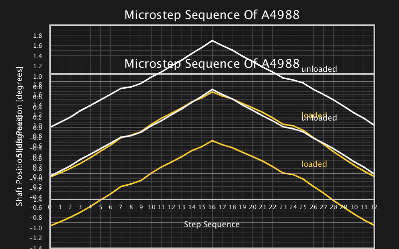
When https://www.machinedesign.com/archive/a ... ping-myths says that the holding torque at 1/2 step is only 70.71% of holding torque at full step, what it really means is that applying a 100% force will cause the motor to "slip a cog", and applying 70.71% that much force will cause the rotor to deviate by an angle equal to 1/2 step. Similarly, applying 38.27% of the "slip a cog" force will cause the rotor to deviate by an angle equal to 1/4 step, and so on, down to applying 0.61% will cause deviation equal to 1/256 step.
What the article fails to say explicitly is that this relationship remains true no matter which direction the rotating field is pointing.
So, it does not make any difference whether you start on a full step position, or 1/4 step, or 1/2 step, or 13/256 step. In every case, a force of 38.27% will cause an angular deviation equal to 1/4 step. If you've commanded 0 (a full step position), you get -1/4 (1/4 step below that). If you've commanded 1/4, you get 0; commanded 1/2, you get 1/4; commanded 3/4, you get 1/2; commanded 1, you get 3/4; and so on, always lagging by an angle of 1/4 step from what you've commanded.
If you care only about relative movements, then if the load is constant, and there's no static friction, and with perfect drive waveforms, none of this is of any concern at all.
The big problem comes when we introduce static friction. In that case I think the term "holding torque" becomes seriously misleading because we don't want to hold a position, we want to change it.
If the static friction is equal to say 2% of the "slip a cog" torque, and we try commanding a move of 1/256 step from current position, then nothing will happen because 1/256 step gives only 0.61% of "slip a cog" torque. If we command 2/256 step, we still get only 1.23% and nothing moves. 3/256 step, 1.84%, still nothing moves. Only when we command a change of 4/256 of a full step do we get enough additional torque, 2.45%, to overcome static friction.
At that point things start to move, the static friction disappears, there's some complicated acceleration/deceleration process, eventually the speed drops to zero again, at which point static friction clicks in, and you have a new physical position that roughly approximates where you intended to be, but is highly unlikely to be within 1/256 of a step of that.
If you repeat the process of commanding a certain increment, over and over again, then "on average" the physical position will track the commanded position, but the physical increments will not be exactly equal to the commanded increments. Instead the physical increments will vary, larger and smaller than the commanded increments, in what may not even be a regular pattern. (Google dripping faucet chaos to see some discussion of that.)
In addition to the static friction problem, there are other issues like nonlinearity caused by the magnetic "detent" and/or imperfect drive currents.
So yeah, there's lots to worry about with stepper motors.
But deciding whether to start your sequence at a full step boundary is not one of them.
At least that's how I think it works.
--Rik