Accuracy of the NEMA 17 0.9°16micro-steps & THK KR2001A

Have questions about the equipment used for macro- or micro- photography? Post those questions in this forum.

Moderators: rjlittlefield, ChrisR, Chris S., Pau

Adalbert
Posts: 2455
Joined: Mon Nov 30, 2015 1:09 pm

Post by Adalbert »

Hello Rik,
OK, firstly I have improved the mounting of the camera :-)

The pattern dependent on the 16 micro-steps looks like follows:
Image
https://farm8.staticflickr.com/7883/470 ... d5b3_o.jpg

- 1: long
- 2-13: OK
- 14: long
- 15,16: short opposite direction

BTW, maybe everything should be shifted by 1 because I have hidden above the extremely large first step:
Image
https://farm8.staticflickr.com/7902/321 ... c9ca_o.jpg

BR, ADi


Image

rjlittlefield
Site Admin
Posts: 23597
Joined: Tue Aug 01, 2006 8:34 am
Location: Richland, Washington State, USA
Contact:

Post by rjlittlefield »

Interesting!

Now you have an unmistakable repeating pattern of 16 microsteps, with a little random noise superimposed on it. This now looks to me like you're getting high quality data about device behavior.

I would characterize this pattern by saying that in each group of 16, the first and last microsteps move a hair backward instead of forward, and those errors are roughly compensated by an unusually large forward movement next to each of the slight backward moves.

So, if you were to step by multiples of 2 microsteps, with the sequence aligned so as to split up the pair of backward microsteps, it looks to me like you'd get a pretty uniform sequence of ~0.0003 mm movements.

--Rik

Edit: fix units, "micron" --> "mm"
Last edited by rjlittlefield on Thu Feb 14, 2019 1:18 pm, edited 1 time in total.

ChrisR
Site Admin
Posts: 8671
Joined: Sat Mar 14, 2009 3:58 am
Location: Near London, UK

Post by ChrisR »

How do you figure that, Rik; he has a block of 4 steps at eg 14 - 17, to avoid?
Last edited by ChrisR on Thu Aug 01, 2019 10:22 am, edited 1 time in total.
Chris R

rjlittlefield
Site Admin
Posts: 23597
Joined: Tue Aug 01, 2006 8:34 am
Location: Richland, Washington State, USA
Contact:

Post by rjlittlefield »

ChrisR wrote:How do you figure that, Rik; he has a block of 4 steps at eg 14 - 17, to avoid?
Steps # 12+13 ~= 14+15 ~= 16+17 ~= 18+19 etc.

--Rik

Adalbert
Posts: 2455
Joined: Mon Nov 30, 2015 1:09 pm

Post by Adalbert »

Hello Chris,
The average values look like follows:
Image
https://farm8.staticflickr.com/7899/401 ... ec7a_o.jpg
BR, ADi
Last edited by Adalbert on Thu Feb 14, 2019 1:15 pm, edited 1 time in total.

ray_parkhurst
Posts: 3431
Joined: Sat Nov 20, 2010 10:40 am
Location: Santa Clara, CA, USA
Contact:

Post by ray_parkhurst »

Is that large negative first step due to a backlash compensation?

mawyatt
Posts: 2497
Joined: Thu Aug 22, 2013 6:54 pm
Location: Clearwater, Florida

Post by mawyatt »

Rik,

Think this is 0.0003mm not 0.0003 microns (0.3nm!).

Best,
Research is like a treasure hunt, you don't know where to look or what you'll find!
~Mike

rjlittlefield
Site Admin
Posts: 23597
Joined: Tue Aug 01, 2006 8:34 am
Location: Richland, Washington State, USA
Contact:

Post by rjlittlefield »

mawyatt wrote:Think this is 0.0003mm not 0.0003 microns (0.3nm!).
Yep, typo fixed, thanks.

--Rik

Adalbert
Posts: 2455
Joined: Mon Nov 30, 2015 1:09 pm

Post by Adalbert »

Hello Ray,
Is that large negative first step due to a backlash compensation?
Yes, this should be the reason.

BTW, I haven’t measured the backlash of this rail because I’ll never start the stack in opposite direction.
And in order to avoid the problem of the first steps I’m moving the rail ( two dummy-steps ) in the direction of the stack at the beginning.
http://www.photomacrography.net/forum/v ... c&start=15

BR, ADi

Adalbert
Posts: 2455
Joined: Mon Nov 30, 2015 1:09 pm

Post by Adalbert »

Hello everybody,
This time one micron with TMC5130.
https://www.photomacrography.net/forum/ ... c&start=45
Image
But I haven’t found the optimal settings for the TMC up to now.
Probably the result can be improved.
BR, ADi

kaleun96
Posts: 270
Joined: Sat Oct 20, 2018 3:47 pm
Location: Stockholm, Sweden

Post by kaleun96 »

Adalbert wrote:Hello everybody,
This time one micron with TMC5130.
https://www.photomacrography.net/forum/ ... c&start=45
Image
But I haven’t found the optimal settings for the TMC up to now.
Probably the result can be improved.
BR, ADi
How do you get these measurements from Zerene? Is there some output from a stack you can export with the estimated offset between each photo?
- Cam

Adalbert
Posts: 2455
Joined: Mon Nov 30, 2015 1:09 pm

Post by Adalbert »

Hi Kaleun96,
Yes, console log.
Please take a look at this thread:
https://www.photomacrography.net/forum/ ... highlight=
BR, ADi

rjlittlefield
Site Admin
Posts: 23597
Joined: Tue Aug 01, 2006 8:34 am
Location: Richland, Washington State, USA
Contact:

Post by rjlittlefield »

kaleun96 wrote:Is there some output from a stack you can export with the estimated offset between each photo?
For users with Prosumer or Professional licenses, File > Save Other > Save Registration Parameters will write a tab-separated-values file that will load directly into Excel.

The file includes the XOffset, YOffset, Scale, and Rotate values for each frame, along with the file name and some other values.

With Student and Personal Edition, the same information can be extracted less conveniently from either the console log or a saved project file.

No matter how you get them, the meaning of these numbers is explained at https://www.photomacrography.net/forum/ ... hp?t=21508 .

For high precision measurements in the micron range, the best method is to mount a patterned target on the rail and track its movement by looking from the side using a high magnification macro setup, as described at https://www.photomacrography.net/forum/ ... hp?t=11519 ("Tiny focus steps: how to make them, how to measure them"), with other applications shown at https://www.photomacrography.net/forum/ ... hp?t=16323 and https://www.photomacrography.net/forum/ ... hp?t=27549 .

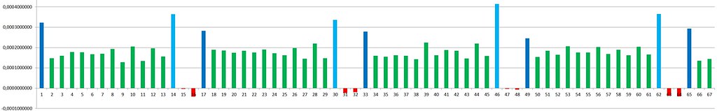
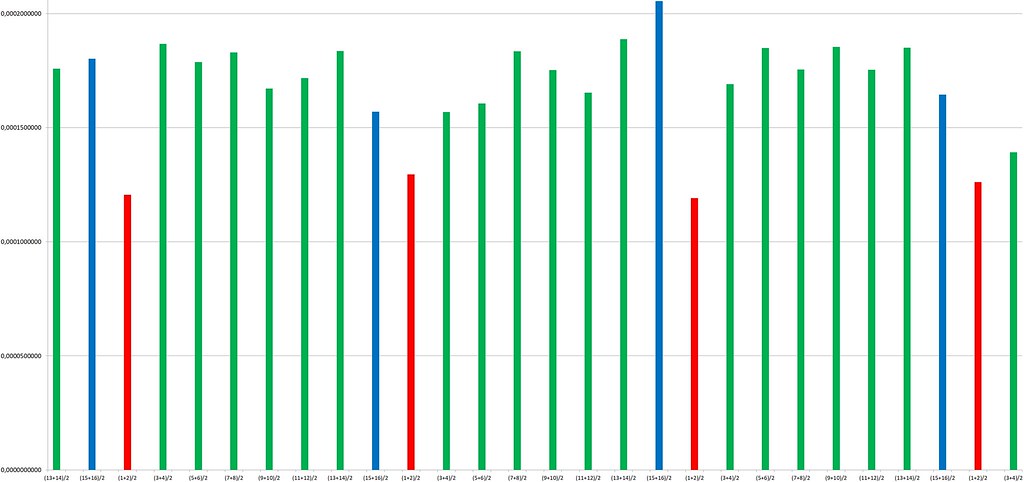
Useful information can also extracted from an ordinary stack, in which case XOffset and YOffset indicate lateral stability such as nutation of the carriage. You can also use frame-to-frame changes in the Scale parameter as an indicator of step size. Using scale as an indicator for step size is much less precise than the look-from-the-side approach, particularly with ordinary photographic subjects rather than specially designed test targets. However, it is almost always available (doesn't work with telecentric optics) and it can yield useful information about system stability and accuracy with no extra setup.

--Rik

kaleun96
Posts: 270
Joined: Sat Oct 20, 2018 3:47 pm
Location: Stockholm, Sweden

Post by kaleun96 »

You guys are great, thanks! I had searched around a bit but wasn't coming up with anything that went into the detail, so I appreciate the explanation Rik!
- Cam

Adalbert
Posts: 2455
Joined: Mon Nov 30, 2015 1:09 pm

Post by Adalbert »

Hello everybody,
This time 0.6 micrometre for the MSPlan 50 / 0.55 and 3 photos a DOF:
Image
BR, ADi

Post Reply Previous topicNext topic