wow, what a setup!!
One thought I have is to put more weight on the "platform" so, for the same differential current, the diplacement will be less, thus making it suitable for higher magnification work. On the other hand, this might be problematic with calibration.
Just some thoughts.
Voice Coil Rail
Moderators: rjlittlefield, ChrisR, Chris S., Pau
-
ray_parkhurst
- Posts: 3439
- Joined: Sat Nov 20, 2010 10:40 am
- Location: Santa Clara, CA, USA
- Contact:
I could easily see this little guy working for 50x or higher. My power supply has a "fine" voltage adjust knob, and wnen using it at 20x I can see almost imperceptible changes in focus across the full knob range, which is ~250mV or half the step size I chose for the 20x example. With my simple DVM arrangement the smallest practical electrical stepsize with good resolution is 10mV. This would correspond to a physical step of 50nm (0.05um). The table on Zerene website only goes up to NA=0.55, with step size of 1.8um, so it seems an available step size of 0.05um is overkill for any practical magnification level. Going to 100mV electrical steps would give 0.5um physical steps with high accuracy.
One thing I worry about is noise from the current source, but that could be easily eliminated by using a large capacitor across the coil. This would also reduce the transient stepping issues when discrete current steps are used rather than continuous as in my implementation. Speakers are designed to have significant dampening to eliminate unwanted audio resonances, so physically they seem an almost ideal motor for this application.
One thing I worry about is noise from the current source, but that could be easily eliminated by using a large capacitor across the coil. This would also reduce the transient stepping issues when discrete current steps are used rather than continuous as in my implementation. Speakers are designed to have significant dampening to eliminate unwanted audio resonances, so physically they seem an almost ideal motor for this application.
ray_parkherst wrote:
Thanks!
This is quite an interesting thread. This AM I found myself doing numerous web searches on voice coil actuators (VCA) to better understand the physics and control of the mechanism as well as the cost and construction of commercial VCAs. Repurposing an old speaker is a very good solution.
Thx mkjzz for starting this thread, and ray for testing!
Keith
Ray can you point me to the method or software used for perspective rendering?then a perspective rendering
Thanks!
This is quite an interesting thread. This AM I found myself doing numerous web searches on voice coil actuators (VCA) to better understand the physics and control of the mechanism as well as the cost and construction of commercial VCAs. Repurposing an old speaker is a very good solution.
Thx mkjzz for starting this thread, and ray for testing!
Keith
-
ray_parkhurst
- Posts: 3439
- Joined: Sat Nov 20, 2010 10:40 am
- Location: Santa Clara, CA, USA
- Contact:
I used Helicon Focus for the 3D rendering. I think Zerene also does this.
I did a bit more testing on the speaker. Turns out the designers built the motor to slightly compress for small voltages up to around 150mV, then expand up to around 500mV, then compress again. I suppose this gives the best overall linearity in this motor.
I tested the speaker over a wider range than my stacking example by changing the resistor to 100 ohms.
Here's the overall displacement curve from 100mV up to 20V, followed by the curve from 500mV to 5V, which is about the same starting point but 30% beyond the range I used for my example. The speaker looks pretty linear over the range I used.


edited to replace the .5-5V graph with .5-10V to show expanded linear range.
I did a bit more testing on the speaker. Turns out the designers built the motor to slightly compress for small voltages up to around 150mV, then expand up to around 500mV, then compress again. I suppose this gives the best overall linearity in this motor.
I tested the speaker over a wider range than my stacking example by changing the resistor to 100 ohms.
Here's the overall displacement curve from 100mV up to 20V, followed by the curve from 500mV to 5V, which is about the same starting point but 30% beyond the range I used for my example. The speaker looks pretty linear over the range I used.
edited to replace the .5-5V graph with .5-10V to show expanded linear range.
Last edited by ray_parkhurst on Thu Apr 13, 2017 7:05 am, edited 1 time in total.
Thanks ray_parkhurst, from your data, I think your power supply can be replaced by a LM317 circuit (google it, very simple circuit), along with cheap (but accurate) digital voltage readout, a precision multi-turn pot with knobs. Hmm, I am ordering these, just to see how it works and experiment with different speakers, etc.
-
rjlittlefield

- Site Admin
- Posts: 23622
- Joined: Tue Aug 01, 2006 8:34 am
- Location: Richland, Washington State, USA
- Contact:
They are quite different functionalities. Helicon Focus uses the depth map to construct a 3D model that can be manipulated interactively in a viewer; Zerene Stacker works directly from the image data to construct off-axis views by re-running the stacking algorithm. If you have simple smooth geometries that you want to view from far off axis, as with Ray's coins, then Helicon's approach is a better match. Zerene Stacker's advantage is that it works well even with arbitrary geometries (think bristly bugs or transparent structures), but you have to stay pretty close to the original axis of the stack.ray_parkhurst wrote:I used Helicon Focus for the 3D rendering. I think Zerene also does this.
--Rik

This is very interesting thread!
Regards Jörgen
You can of course use the depth map created by Zerene, import it to Adobe PS to create a 3D model. This is one example that I uploaded to Sketchfab https://skfb.ly/ZVzRrjlittlefield wrote:They are quite different functionalities. Helicon Focus uses the depth map to construct a 3D model that can be manipulated interactively in a viewerray_parkhurst wrote:I used Helicon Focus for the 3D rendering. I think Zerene also does this.
--Rik
Regards Jörgen
Jörgen Hellberg, my webbsite www.hellberg.photo

Jorge,JH wrote:This is very interesting thread!
You can of course use the depth map created by Zerene, import it to Adobe PS to create a 3D model. This is one example that I uploaded to Sketchfab https://skfb.ly/ZVzRrjlittlefield wrote:They are quite different functionalities. Helicon Focus uses the depth map to construct a 3D model that can be manipulated interactively in a viewerray_parkhurst wrote:I used Helicon Focus for the 3D rendering. I think Zerene also does this.
--Rik
Regards Jörgen
That is very nice. Would appreciate a description on how you went about doing this, I think other members would be interested as well.
Probably a good subject for another thread though.
Best,
Mike
-
TheLostVertex
- Posts: 318
- Joined: Thu Sep 22, 2011 9:55 am
- Location: Florida
I know you are trying to clear up a possible misunderstanding, but I should still mention. With the help of a secondary program, Zerene can do the same as helicon. The "Generate depth map" option in the settings is all you need.rjlittlefield wrote:They are quite different functionalities. Helicon Focus uses the depth map to construct a 3D model that can be manipulated interactively in a viewer; Zerene Stacker works directly from the image data to construct off-axis views by re-running the stacking algorithm. If you have simple smooth geometries that you want to view from far off axis, as with Ray's coins, then Helicon's approach is a better match. Zerene Stacker's advantage is that it works well even with arbitrary geometries (think bristly bugs or transparent structures), but you have to stay pretty close to the original axis of the stack.ray_parkhurst wrote:I used Helicon Focus for the 3D rendering. I think Zerene also does this.
--Rik
See this post and my follow up post for an example http://photomacrography.net/forum/viewt ... 872#143872 The main differences are the example I generated for Keith was culled to the subject he was interested in, and I did not bother to apply the actual image data as a texture. Helicon's method is an automatic method of applying the depthmap and image to a 3d surface. See https://en.wikipedia.org/wiki/Displacement_mapping
-
ray_parkhurst
- Posts: 3439
- Joined: Sat Nov 20, 2010 10:40 am
- Location: Santa Clara, CA, USA
- Contact:
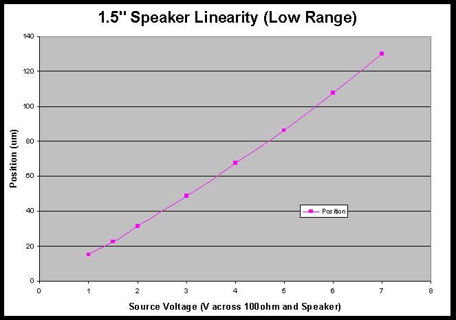
I tested a couple more, smaller speakers, and found one that is very suitable for this application. It's a 1.5" full-range. It is showing no signs of compression up to almost 450um displacement. This is more than I need, so I did not change to a smaller resistor to push further. Also shown below is the curve up to 7V/130um displacement, showing good linearity in that range. The absolute positional error is +/-5% from 1...7V:

Built a variable voltage power supply for this. Since, thanks to @ray_parkhusrt, current drawn from power supply is not much, so a LM317 is more than adequate for this. Though I did not try to push it up to 0.5A, this circuit should be capable of it, a heat sink might be needed at high current.
I can not believe I do not have through-hole capacitor, so I am not using them in my construction. I was going to use that multi-turn POT, but it was DOA, so I have to use a precision POT with (almost) 360 degree turns. The blue 7-seg display is a voltage readout component, you can get it easily on eBay (I think).
Vout = 1.25 * (1+ R2/R1) and is limited by Vin - 3V (approximately)
In my case, I used 5K POT for R2 and 1K for R1, this means Vout is between 1.25V and 7.5V, if you use a 10K POT and your power supply is 24V, you can get 1.25 to 13.75V
A multi-turn (10 turn) POT should be better because it allows you to do fine tuning.
C1, C3 should be some large electrolytic capacitor like 47uf to 100uf and C2, C4 can be 0.1uf capacitor
[added]Forgot to mention, the speaker is a full range long throw one[/added]
Peter, Ray,
Great stuff!! You will eventually want to go to current mode for precision. This is simply because the Voice Coil Magnetic Field which makes it move is proportional to current not voltage.
You can approximate a current source as Ray has done, but if you are going to the trouble of creating a custom variable voltage source, you really should create a variable current source.
When you start looking at repeatability and linearity in fine detail, small voltage drops across the Voice Coil will affect the current thru the coil and thus the magnetic field and position. This will not affect a current source implementation!
For the same amount of cost and effort you can create a simple current source which will be at least a 100 to 1000 times more precise for this application.
In 1980 we built a Moving Mirror Michelson Interferometer utilizing a Voice Coil for the moving mirror, and we used a Current Source to drive the coil for precision positioning. This worked well and the instrument went into full production, and may still be in production today.
Should mention another advantage of a Current Source is the maximum voltage necessary to force the current thru the Voice Coil is not the maximum current times the series resistor, it's simply the voltage drop across the sense resistor (small) and another few volts for the active current device.
For example, pumping 500 milliamps thru a 100 resistor takes at least 50 volts! The same 500 milliamp condition for a current source may require less 10 volts! If fact the current source can deliver more current without increasing the supply voltage if the sense resistor is lowered, whereas a voltage source must increase the voltage, or lower the series resistor. Power dissipation is lower for the current source because the input supply voltage required is so much lower, in the above example 25 watts (0.5*50) vs. 5 watts (0.5*10)!!
Anyway, many reasons to go the current source method, considering the precision, power dissipation and it doesn't really cost significantly more (<$2)!!
Happy Easter,
Mike
Last edited by mawyatt on Sun Apr 16, 2017 9:47 am, edited 1 time in total.
