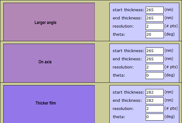
That's what I thought too. But the calculator disagrees. In fact the calculator's shift has the opposite sign. Increasing the angle causes the calculator's spectrum to shift right, while increasing the maximum film thickness causes it to shift left. I'm very confused.ChrisR wrote:I think the color at 20º should match what you get at
(original wavelength)/cos 20º = 282nm .
The paper at https://www.osapublishing.org/viewmedia.cfm?id=79472 supposedly explains how the calculator models the physics of the film reflection, but I haven't read it in enough detail to resolve my confusion.
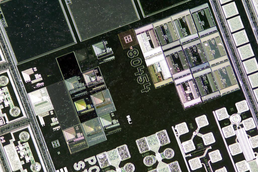
In any case, here's an animation of the chip as photographed with two angles of light:
Each of the two frames of this animation was a single camera exposure, shot with a 20X objective, using a non-diffused Jansjö lamp.
Despite the obvious change in apparent geometry, nothing physically changed between the two exposures except for the angle of the light.
The difference in aspect ratio between the two frames is entirely due to the "utilized aperture" effect. Physically the slide is at a fixed angle, tilted about 22 degrees with respect to the objective. In one frame the light is positioned above the slide, so that the reflection enters roughly the center of the objective. In the other frame, the light is positioned at a much lower angle, so that the reflection barely enters the edge of the objective. Effectively, the slide is being viewed at a lot lower angle in the second case, and the difference in aspect ratio is just perspective foreshortening corresponding to the different virtual viewing angle.
In both cases, the narrow angle of the illumination greatly stops down the objective, resulting in greatly increased DOF and correspondingly reduced resolution for focused detail.
--Rik