Choice of color temperature for the power LED flash module.

Have questions about the equipment used for macro- or micro- photography? Post those questions in this forum.

Moderators: rjlittlefield, ChrisR, Chris S., Pau

fotoopa
Posts: 194
Joined: Sat Dec 14, 2013 3:14 am
Location: Belgium
Contact:

Post by fotoopa »

The new high power led module is ready for use. The first test with the gray card is done. The flash time with the 10 channels on is 350 us versus 2400 us compared to the previous version. The current per channel is set to 1200 mA or 12A total @ 39V. The maximum current can go up to 1400 mA per channel.
The LEDs used are Cree LEDs CXA 1830@4000K. This temperature is lower than my previous version. I have set a new white balance in the D7100 as P4. The flash time can go up to 30 ms per shot at a step rate of 2.5 sec. Here there is plenty of time for recharging the 40.000 uF capacitors. My normal cycle time is 2.7 seconds per shot. I may hold this cycle indefinitely. The LEDs are not even hot. This is due to the very low duty cycle. In preview mode, I use 1 us on/511 us off cycle. Same for the WB setting. The RS422 driver works fine. Over a distance of 5m is the delay only a few ns. With 10 channels I can adjust the light direction fine.

Image
500W power LED module in use P8126452 by Frans, on Flickr

I take now first a week off. My two youngest grandchildren come in vacation to us. My darkroom space is just closed ...during this period.

Frans.

Chris S.
Site Admin
Posts: 4044
Joined: Sun Apr 05, 2009 9:55 pm
Location: Ohio, USA

Post by Chris S. »

Fascinating update, Frans! :D Thanks so much for keeping us in the loop.

Perhaps oddly, my brain, to grasp your post, requires conversion from metric time units to fractions of a second, and a bit of rounding. Your notation is surely superior; my brain's way of understanding is likely just old-fashioned. But in case other members have similarly old-fashioned brains, I hope you won't mind if me restate part of your post in the style I grasp most easily (my substitutions of rounded fractions for Frans' precise metric references are boldfaced):
fotoopa wrote:
  • The new high power led module is ready for use. The first test with the gray card is done. The flash time with the 10 channels on is 1/3000 second, versus 1/400 second in the previous version. The current per channel is set to 1200 mA or 12A total @ 39V. The maximum current can go up to 1400 mA per channel.

    The LEDs used are Cree LEDs CXA 1830@4000K. This temperature is lower than my previous version. I have set a new white balance in the D7100 as P4. The flash time can go up to 1/30 second per shot at a step rate of 2.5 sec. Here there is plenty of time for recharging the 40.000 uF capacitors. My normal cycle time is 2.7 seconds per shot. I may hold this cycle indefinitely. The LEDs are not even hot. This is due to the very low duty cycle. In preview mode, I cycle between 1/1 millionth second on and 1/2000 second off. Same for the WB setting. The RS422 driver works fine. Over a distance of 5m is the delay only a few ns. With 10 channels I can adjust the light direction fine.
For me, you've presented two especially notable points.

One is that you've reduced the LED "flash" time from about 1/400 second to about 1/3000 second. I've seen a number of LED units labeled as "flash," but considered the term a misnomer--most might more fairly be described as "short-duration continuous light," because they are not brief enough to stop significant motion. But your 1/3000 second, to my mind, crosses a watershed into what can much more honestly be called "flash." A duration of 1/3000 certainly can, in many situations, freeze motion. And you have, with seeming ease, dropped light duration by an order of magnitude. If you eventually drop another order of magnitude, you'll be solidly into the domain of short-duration flash.

Another is your exploration of "persistence of vision"--both for the human eye and for your camera's white balance (and, if I infer correctly, live view). That you can use both the eye and camera functions with a cycle of 1/millionth second on and 1/2000 second off is a hugely useful data point. With this cycle, you're getting the functionality of continuous light, combined with the low heat output of very brief on states--the best of all worlds. So far as I know, very few data points about this exist in the public domain. Your publication of the values you find useful serves as a starting point for anyone else interested in similar experiments.

This said, I have a question: Have you measured light output to characterize potential latency? I do wonder if actual light output might cycle less rapidly than your electronic inputs imply.

Hope you have a wonderful time with your grandchildren!

Cheers, and very best regards,

--Chris S.

fotoopa
Posts: 194
Joined: Sat Dec 14, 2013 3:14 am
Location: Belgium
Contact:

Post by fotoopa »

Thanks Chris for clarifying my times used. I'm so busy with my project that I did not attention.
Chris S. wrote:For me, you've presented two especially notable points.

One is that you've reduced the LED "flash" time from about 1/400 second to about 1/3000 second. I've seen a number of LED units labeled as "flash," but considered the term a misnomer--most might more fairly be described as "short-duration continuous light," because they are not brief enough to stop significant motion. But your 1/3000 second, to my mind, crosses a watershed into what can much more honestly be called "flash." A duration of 1/3000 certainly can, in many situations, freeze motion. And you have, with seeming ease, dropped light duration by an order of magnitude. If you eventually drop another order of magnitude, you'll be solidly into the domain of short-duration flash..
Precisely, around 350us you should consider this as flash times. The flash times previously used in my recordings of flying insects were always around the 350 us ( manual power set at 1/32 bij the SB-80-DX). The was sufficient to freeze the wing movements. LEDs have virtually no delay, the light shape is a block shape. In an ordinary flash is the shape less uniform. The rise time at a regular flash is longer and the light output will gradually decrease more towards the end.
Chris S. wrote:Another is your exploration of "persistence of vision"--both for the human eye and for your camera's white balance (and, if I infer correctly, live view). That you can use both the eye and camera functions with a cycle of 1/millionth second on and 1/2000 second off is a hugely useful data point. With this cycle, you're getting the functionality of continuous light, combined with the low heat output of very brief on states--the best of all worlds. So far as I know, very few data points about this exist in the public domain. Your publication of the values you find useful serves as a starting point for anyone else interested in similar experiments.
This mode is very important for the settings of the stacking module and the camera WB. There are a number of elements that play a role and who depend on camera. For live view mode, the refresh rate must be sufficiently high otherwise you see light flickering in your image. Therefore, I need to set the refresh rate to 512 us (2kHz) for the Nikon D7100 camera. Then you have the duty cycle for the LEDs. The lower that can be held, the less heating. I use this mode also for the WB setting. Here, the light intensity should not be too high to be able to perform a calibration. On the other hand the current in the LEDs must have the same value to be sure to obtain the same color temperature. That's why I Always send 1200 mA through the LEDs in any mode. Only the pulse widths differ.
Chris S. wrote:This said, I have a question: Have you measured light output to characterize potential latency? I do wonder if actual light output might cycle less rapidly than your electronic inputs imply.
Not yet via a photo diode. I have not thought of because I expect no delay. I will sometimes measure, I have here a former setup. I've measured the delay of the LED current with respect to the digital control signal (inclusief the RS422 lines over 5m). The rise time is very fast, the fall time slower. This is because the IRF540 turned off slower( ~1us) due to the gate capacitance. I made a test ( gray card) with 10 channels and 5 channels on. The pulse width must be go from 350 us to 700 us for the same result (same WB, same level RGB on the D7100 picture: 128,128,128)
Considering I need only flash times around 1/2000 sec max, you can take much faster images. That 2.5 second setting is for the file transfer to the computer. If you want 10 frames per second recording, the flash can do this.

Frans.

fotoopa
Posts: 194
Joined: Sat Dec 14, 2013 3:14 am
Location: Belgium
Contact:

Post by fotoopa »

Chris S. wrote:I have a question: Have you measured light output to characterize potential latency? I do wonder if actual light output might cycle less rapidly than your electronic inputs imply.
I just made the measurements. For this I use the BAW34 photodiode with a resistor in series 1500 ohm. On the whole, there is a DC voltage of 7.8V. To measure the light I measure the voltage across the 1500 ohm resistor. The measuring distance is increased in order to have no saturation (100 mm). The light output of the LED flash is perfectly flat over the entire controller pulse. There is a slight delay at the start and at the end is the falling edge slightly slower (capacity from gate IRF540 Fets). The rising edge is made slower at the start by adding a small capacity precisely with the intention to make it slightly slower. This is seen more clearly at a pulse width of 10 us.

Image
power_leds_350us by Frans, on Flickr

Image
power_leds_10us by Frans, on Flickr

The LED output is therefore to be considered perfectly flat and the delay of the entire circuit including the RS422 driver is minimal and constant.

Frans.
Last edited by fotoopa on Sat Aug 13, 2016 10:54 am, edited 1 time in total.

mawyatt
Posts: 2497
Joined: Thu Aug 22, 2013 6:54 pm
Location: Clearwater, Florida

Post by mawyatt »

Very nice!!!

mjkzz
Posts: 1689
Joined: Wed Jul 01, 2015 3:38 pm
Location: California/Shenzhen
Contact:

Post by mjkzz »

OMG, this is super awesome!

Just one thought, when I used sound card to measure flash durations, I find it more accurate when a small resistor is wired in parallel with the photodiode. That makes response time faster, the rising edge is steeper, the falling edge depends on characteristic of Xeon tube.

Also the photodiode is reverse biased so that junction capacitance is lower.

I do not know exact circuit you have, but if the other end of the resistor is ground and the other lead of photodiode is also ground, you are wiring them in parallel instead of in series.

But anyway, essentially, a photodiode and a resistor forms an RC circuit due to the junction capacitance of diode. So a smaller resistor might reduce response time of the RC circuit. I am curious if the delay caused by this RC circuit is significant. If it is significant, then the delay could be a characteristic of your measuring system instead of the system being measured.

Just a thought . . .

mawyatt
Posts: 2497
Joined: Thu Aug 22, 2013 6:54 pm
Location: Clearwater, Florida

Post by mawyatt »

The resistor should be in parallel with photo diode. If the diode is not reversed biased, the junction capacitance will be higher. Any type of scope probe you use will add capacitance, significant in many cases. The old Tektronix scope probes we used had about 10pF of input capacitance.

The best way to minimize the effects of probe and diode capacitance is to use a small parallel resistor, or use a transimpedance amplifier. Of course this can get complicated.

If you can use near the most sensitive input of your scope, then you can use a smaller resistor and mitigate the effects of these capacitances.

BTW a 1N4148 diode makes a pretty good low sensitivity unbiased photo detector, suspect a 1N914 would be even better due to the construction. Both of these diodes are very cheap.

BTW the individual circuit time constants follow the root sum square rule, so if you calculate each individual circuit time constant, and there is a 3 or 4 separation you can ignore the shorter time constant in most cases. Your overall circuit time constant will be dictated by the longest.

Best,

Mike

fotoopa
Posts: 194
Joined: Sat Dec 14, 2013 3:14 am
Location: Belgium
Contact:

Post by fotoopa »

Thanks for the info mjkzz & mawyat.

I have the BPW34 reversed via 1500 ohm and the 7.8V dc over both. There is a delay but it is very small. My greater delay came from the current control loop and especially the FET. The delay between the current through the LED and the light is very small including the delay by measuring the BPW34 (not BAW34 as on the picture). In order to demonstrate this, I have now made a measurement of the current through the LED and the light on the photo diode.

Image
Led current and light output 10 us pulse. by Frans, on Flickr

Here you see that there is relatively little delay due to the photo diode or the LED itself. The normal pulse width is at least 350 us. Then the delays are practically negligible.

Update:

The used photodiode is the BPW34 and not the BAW34!

mawyatt
Posts: 2497
Joined: Thu Aug 22, 2013 6:54 pm
Location: Clearwater, Florida

Post by mawyatt »

fotoopa,

Nice, this is what you should expect. The current is what operates the LED.

-7.8v across the photo diode should minimize it's capacitance and 1500 ohms is a reasonably low resistance value, so you should have a relatively low total time constant, which your plots show!!

Best,

Mike

mawyatt
Posts: 2497
Joined: Thu Aug 22, 2013 6:54 pm
Location: Clearwater, Florida

Post by mawyatt »

The longer delays you are showing most likely are due to the Miller effects in the Output FET and driver. Large FETs like you are using require a large amount of charge be transferred into the gate to turn the channel on, and removed to turn it off again. Most circuits are better at turning FETs off than on and you can see this is different rise and fall times.

Since transferring charge as a function of time is current (I=dq/dt), you can analyze circuits without the need for SPICE by hand and get pretty good estimates. Some FETs have the charge specified in the data sheet, so the task is easy, others specify the capacitance which must be integrated which can make it a little harder.

Anyway a common circuit technique to speed these FETS (and Bipolars) up is to use a Cascode circuit which reduces the Miller effect, this is at the expense of more standoff voltage when the FET "switch" is on. Nothing is free in electrical engineering, you have to pay somewhere :>)

Sorry to bore you with all this, but these are a few of the techniques used to speed up pulsed current circuits.

Best,

Mike

mjkzz
Posts: 1689
Joined: Wed Jul 01, 2015 3:38 pm
Location: California/Shenzhen
Contact:

Post by mjkzz »

ah, this is much better. but I am still puzzled that there should not be any phase shift across the resistor, so measuring voltage across the resistor should have same result as measuring current through it, yet the two measuring results differ this much.

Of course, one explanation is that, the whole circuit is NOT a simple RC circuit, a lot is going on.

But it seems measuring current in this case is a sound approach because, like mawyatt said, photodiodes are essentially a current device, we can have a better measurement by measuring current it generates.

But your setup and design are AWESOME!!!

mjkzz
Posts: 1689
Joined: Wed Jul 01, 2015 3:38 pm
Location: California/Shenzhen
Contact:

Post by mjkzz »

sorry, did not read it correctly, ignore last post, I thought you were measuring current through the photodiode.

In this case, I agree, there is little delay (but there is some due to equivalent RC circuit) between LEDs on and detection of it. [edit] this also means the delay caused by RC circuit is NOT significant enough. Now after getting the right part number, BPW34, the data sheets indicates junction capacitance is about 25pn (typical under 3V reverse bias), so the delay measured seems about right.[/edit]

Again great results and great setup.

fotoopa
Posts: 194
Joined: Sat Dec 14, 2013 3:14 am
Location: Belgium
Contact:

Post by fotoopa »

Thanks again!

To make things even clarify I drew a diagram of a complete LED control channel. I made some additional measurements so you can better see some delays. First, the electrical schema:

Image
led 10_basis_shema by Frans, on Flickr

The signal starts from the FPGA to the RS422 transceiver and then to the driver stage. With a pulse duration of 10 us I first measure the delay at the RS422 output:

Image
led 10_basis_fpga_rs422_10us by Frans, on Flickr

Signal looks good, just look at the two edges in closeup:
First the rising edge:
Image
led 10_basis_fpga_rs422 by Frans, on Flickr

Then the falling edge:

Image
led 10_basis_fpga_rs422_neg_edge by Frans, on Flickr

With 60 and 44 nsec the delays are very small. The distance between transmitter and receiver is 5 m. Now we proceed to the first transistor base:

Image
led 10_basis_fpga_T2_base by Frans, on Flickr

The rising edge looks good but the falling edge has already quite a bit of delay. The cause lies partially in the choice of R9 and R11. Here, it may therefore be better done with lower values. Now we take a look at the output collector of the transistor T2:

Image
led 10_basis_fpga_T2_collector by Frans, on Flickr

Little surprise, delays are similar. Finally the current through the FET by measuring the voltage across R14 and R15:

Image
led 10_basis_fpga_led_current by Frans, on Flickr

The total delay is now approximately 2.3 us. For this application, certainly no problem.

Another note:
The control voltage of the FET circuits is 10.5V. Together with R5 and R10, they strongly determine the stability of the current control loop. C6, now 470 pF is rather high, I had no other value than 220 pF which was rather too low. The entire circuit can still improve. But he is fully built in and will remain so. These measurements help hopefully to understand a few things. The base is Always: use single-sided PCB and standard low cost components.

Update:
Drawing corrected (position 5m RS422 cable).
Frans.
Last edited by fotoopa on Sun Aug 28, 2016 2:23 am, edited 1 time in total.

fotoopa
Posts: 194
Joined: Sat Dec 14, 2013 3:14 am
Location: Belgium
Contact:

Post by fotoopa »

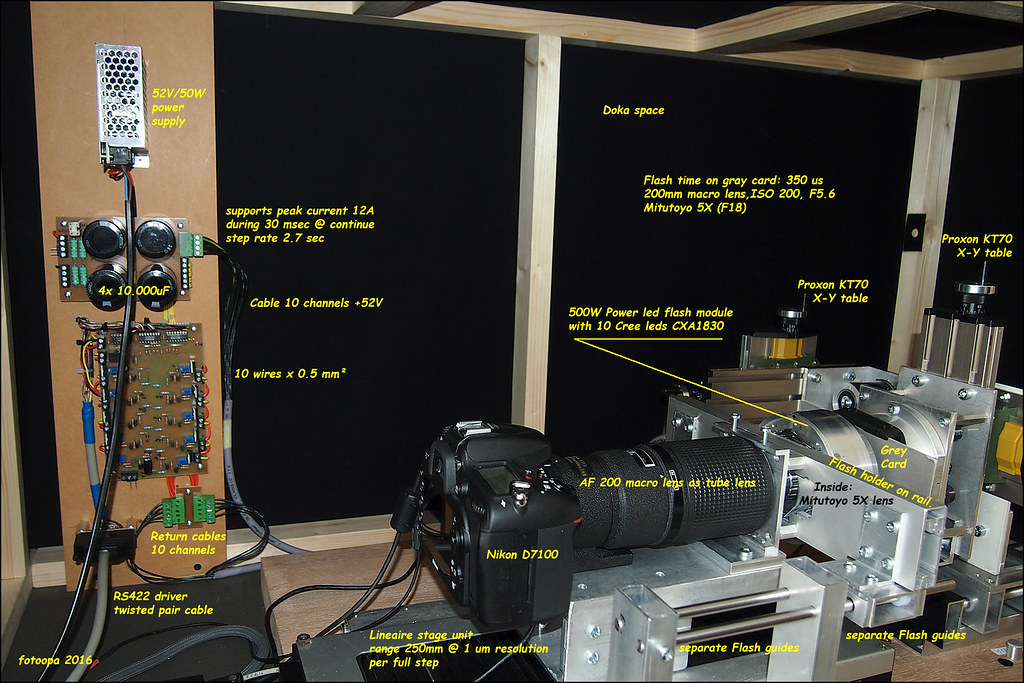
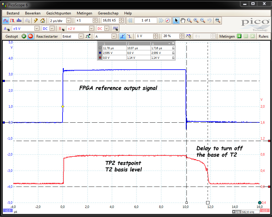
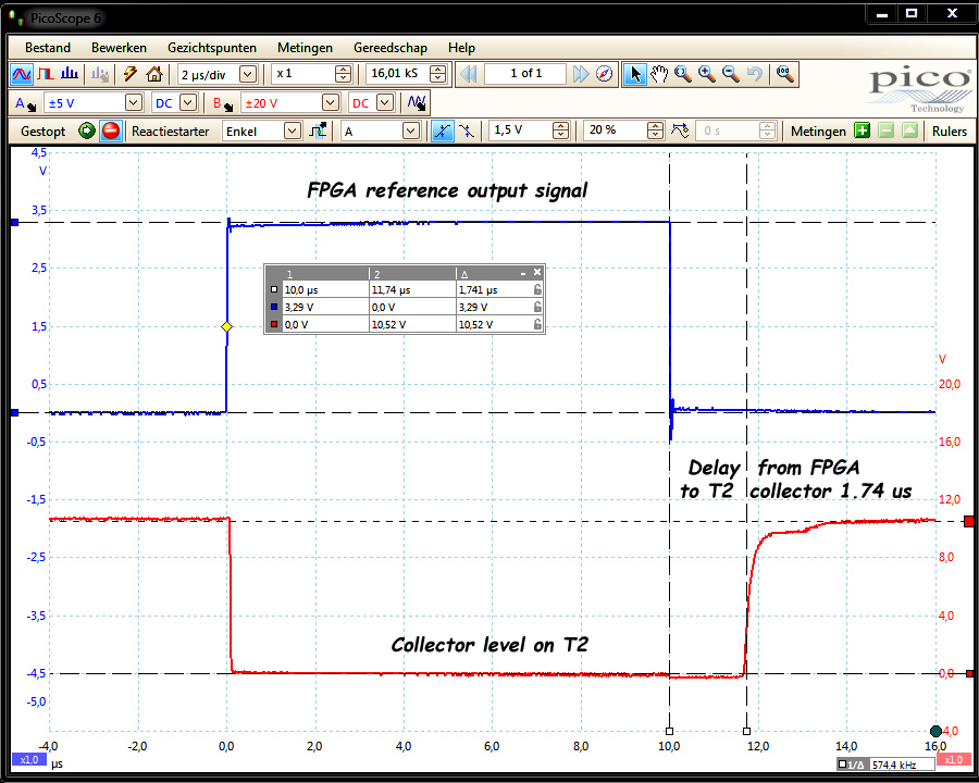
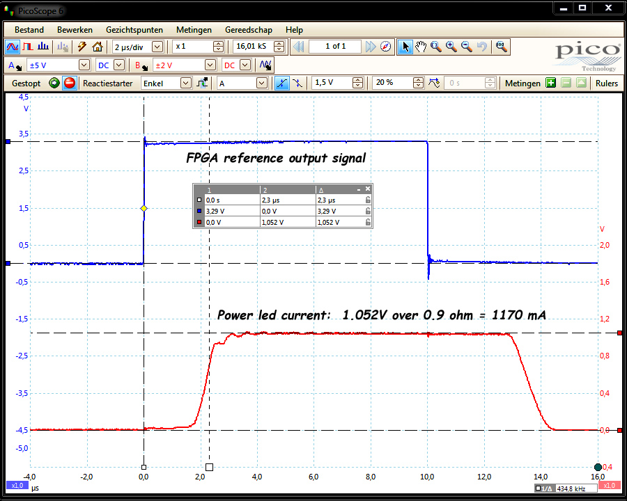
First use and testing of the 10 ch flash LED module.
With 10 channels the lighting direction can be changed. For this, the exposure times for each channel should be adjusted and the connection sequence must be able to change.
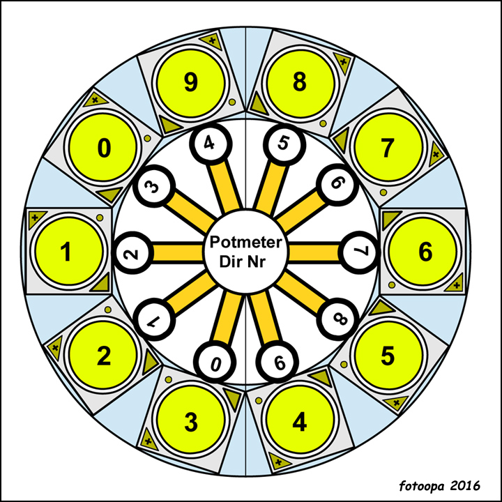
Rotation principle of the 10 ch LEDs:

Image
Rotation principle of the 10 ch LEDs. by Frans, on Flickr

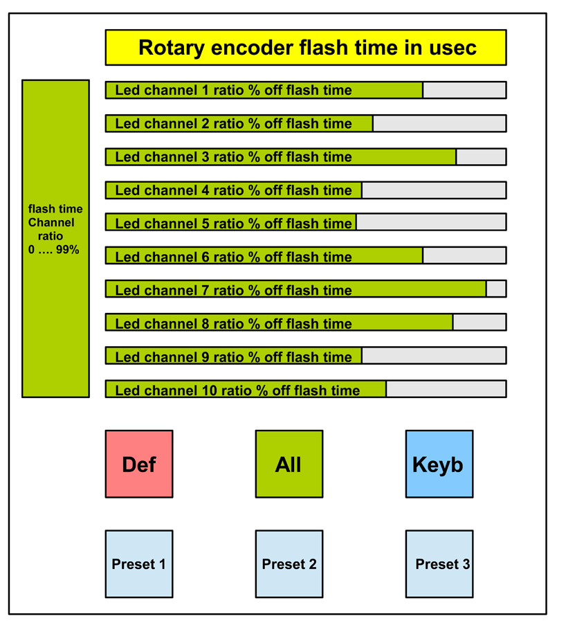
Rotation principle of the 10 ch LEDs. Each LED can be connected to any output register. As a result, the exposure direction can be changed. The individual LED times are sent from a preset table. These values should not change, only the rotation potmeter in order to obtain a different direction.

How to driving the 10 ch LED module? The values of the individual channels are expressed in% of the total time. Each channel has a ratio. By now changing the total time you preserve the Original exposure ratio. Slightly more or slightly less exposure can be done via the Time rotary encoder knob. The individual time of each channel is recalculated by the FPGA real time.

A few special push buttons simplify the configuration work.
There is a DEF push button to restore the default values.
An All push button set all channels at the same key entry value.
You can also manually change each channel individually.
These manual values can restore back at any time.

You can also insert a number of presets. These are programmed values for each channel. They are used when you want to give a direction to light. These presets reduce the light output up to 50%, 25% or 12.5%. Thus, the strength of the direction is determined.
Image
Driving the 10 ch LED module. by Frans, on Flickr

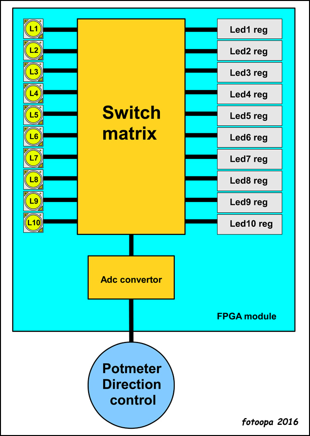
Matrix principle for the 10 ch LEDs. A potentiometer sends an analog value to the AD converter. The FPGA calculated from this 10 directions. The digital information of the direction is used to control a matrix. Thus, each LED can be re-connected to each output register. This results in a rotation.

Image
Matrix principle for the 10 ch LEDs. by Frans, on Flickr

Now time for the field test. Here all leds are at full power. No light direction, this gives a more flat image with less contrast:

Image
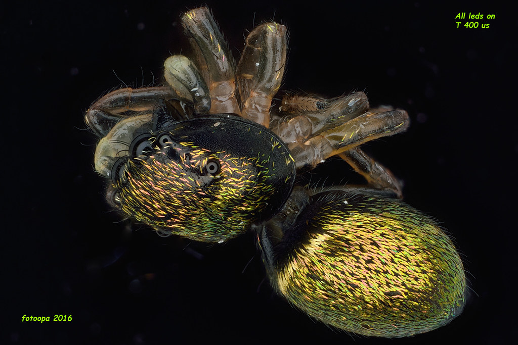
Exposure with all leds @ max, no light direction used. by Frans, on Flickr

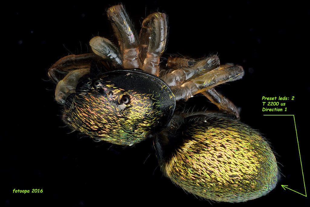
The next recording is done with a preset 25% power distribution over the 10 LEDs. Giving the flash time different values, this creates a direction. Values are presets, just load them via one push button. The DIR potentiometer change the output sequence, thus the light direction. Here the direction is set to D1, not so good choice, the eyes are hardly exposed:

Image
Experiments with changing the exposure direction to D1 by Frans, on Flickr

Now let's change the direction of the potentiometer to D6:

Image
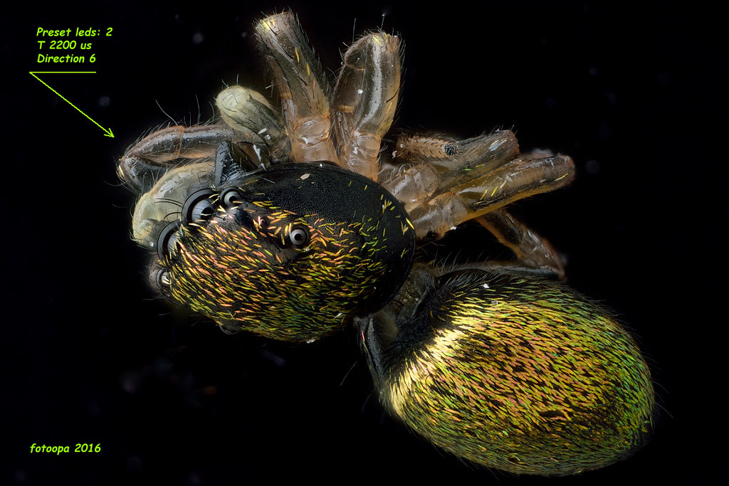
Experiments with changing the exposure direction @ D6. by Frans, on Flickr

This is definitely better. My higher led power allows to make optimal direction profiles and yet still be used short flash times. This flash led module version gives me new opportunities.

Frans.

ChrisR
Site Admin
Posts: 8671
Joined: Sat Mar 14, 2009 3:58 am
Location: Near London, UK

Post by ChrisR »

A lot of work, but very impressive.=D>
I expect you thought of using a joystick for the lighting direction?
Chris R

Post Reply Previous topicNext topic