False color and detail/DOF from shiny metal

A forum to ask questions, post setups, and generally discuss anything having to do with photomacrography and photomicroscopy.

Moderators: rjlittlefield, ChrisR, Chris S., Pau

rjlittlefield
Site Admin
Posts: 23598
Joined: Tue Aug 01, 2006 8:34 am
Location: Richland, Washington State, USA
Contact:

Post by rjlittlefield »

ChrisR wrote:I wonder is a more or less telecentric setup would show the effect identically.
These effects occur at image center, where telecentricity is not an issue.
I remember the highlights appearing to be displaced away from the source of the light.
I'm sure that's related. Just from basic ray theory, we know that OOF details will get shifted one way or another depending on what path the light arrives from. With a wide aperture objective, that path can vary quite a bit depending on both location of the light and local slope of the subject. Because it's dependent on local slope of the subject, 3D subjects often seem to rock or to change shape as you fly focus up and down. We discussed some of this earlier at http://www.photomacrography.net/forum/v ... hp?t=16736.

--Rik

Chris S.
Site Admin
Posts: 4044
Joined: Sun Apr 05, 2009 9:55 pm
Location: Ohio, USA

Post by Chris S. »

What a fascinating and needed thread, Rik! Yay for bringing this up and undertaking such useful experiments.

I've seen this sort of color phenomenon so often with metal surfaces that I'd be startled not to see it. But my eyes opened wide the first time I saw it with black carbon. Perhaps I shouldn't have been surprised, as a quick search showed that iridescence has been observed repeatedly in carbon nanostructures. But so far as I checked, this phenomenon did not seem to be well-characterized.

With a few carbon subjects, I've examined the iridescence with some care--partly because it's an interesting phenomenon, and partly for insight into whether the colors conveyed information about the carbon or were just the result of aberrations in my lenses. My sense is that most of what I've seen in carbon--and probably what has been demonstrated with metal rulers in this thread--is iridescence due to diffraction and interference. (Thus agreeing with Rik's sense of it.)

If so, we might want to use a term other than "false colors" for these phenomena. These colors may be confusing to us at present, but there is the possibility that they reveal, rather than obscure, characteristics of our subjects.

Here is airborne soot from burning pine straw, collected on a glass-fiber air filter, shot with diffuse (though directional and fairly oblique) flash illumination. It is a crop from a stack shot with a Nikon Planapo 4x NA 0.20 objective. Note the near absence of color in the carbon soot:

Image

I made the above image to support a friend's research in airborne particulates, and used diffuse light to tame reflection and refraction from the glass fibers. But it was interesting to me that similar images with less diffuse illumination showed iridescence in the carbon, so somewhat later, I revisited the subject at higher magnification with much less diffuse light. Here is a higher-magnification shot of a different spot on the same filter with pine-straw soot. In this case, I used halogen light through an undiffused fiber optic light guide. It is cross-polarized in order to reduce reflection off the glass fibers, but to my eye, this did not much change the colored spots. This is a crop from a 157-image stack shot with a 100x NA 0.70 Mitutoyo objective.

What a panoply of apparent color on the carbon soot!

Image

This color did not much change, to my eye, as elements moved in and out of focus. (Though it's beyond my ability to keep 157 images in mind as I scroll through them--will try assembling this group into slabs, which may either support or weaken the observation.)

Cheers,

--Chris

ChrisR
Site Admin
Posts: 8671
Joined: Sat Mar 14, 2009 3:58 am
Location: Near London, UK

Post by ChrisR »

Rik wrote:Just from basic ray theory, we know that OOF details will get shifted one way or another depending on what path the light arrives from.
How so? A dot on the subject becomes a concentric blob on the sensor. Why should it get displaced laterally? (assuming no magnification changes)

Then, "path from the light arrives from" - source to subject? How so?
How is a point on a subject which is illuminated from one direction, different from a self-illuminated point? Unless we're looking at reflection or diffraction effects coming from the interaction between the surface plane of the point, and the incident light?
The line of thought may have some mileage for sparklies, going from how Diffractive Optics work. Looking closely ( jml 20x objective held to my eye) at the surface of a CD and tilting it such that a surface speck moves left to right, the diffraction colours coming from incident light, move right to left, "past" the speck.
(Dark Side Of The Moon, ..)

I think I need another visit to Wikipedia - Basic image formation :oops:

ChrisR
Site Admin
Posts: 8671
Joined: Sat Mar 14, 2009 3:58 am
Location: Near London, UK

Post by ChrisR »

Does the "miraculous" (divine light?) extra DOF with directional light source depend on the orientation of the brushed scratches in the steel?

I'm reminded of something I only ever understood sllightly, about how astronomers get better than theoretical resolution from a diffraction effect. Do the scratches just happen to be at a critical pitch?
What initially looks like detail in the area outside the diffused-light in-focus band could just be small sized, high contrast, constructive interference rubbish.

(Or I'm talking rubbish and my interference is destructive..)

enricosavazzi
Posts: 1475
Joined: Sat Nov 21, 2009 2:41 pm
Location: Västerås, Sweden
Contact:

Post by enricosavazzi »

ChrisR wrote:...
What initially looks like detail in the area outside the diffused-light in-focus band could just be small sized, high contrast, constructive interference rubbish.
...
That could be the explanation. If we know that the particular subject area is out of focus, any detail that appears in focus in that area should be an artifact, caused by diffraction and/or interference, or by the sensor-to-final-image processing chain. Or by lensing.

A lensing effect by concave reflecting surfaces or translucent structures of uneven thickness might also create artifacts with fine detail visible where nothing should be in focus. This would need to be classified in the reflection or refraction categories, respectively. In practice, this would be equivalent to a composite optical system, with parts of the subject focusing reflected/transmitted light into an aerial image, and the camera/microscope objective picking up and magnifying this aerial image.
--ES

ChrisR
Site Admin
Posts: 8671
Joined: Sat Mar 14, 2009 3:58 am
Location: Near London, UK

Post by ChrisR »

So in the most general way, light is coming from out-of-focus parts of the subject but forming an image because it happens to arrive together at the sensor.
I think we can include diffraction as a possible contributing source? It seems plausible that machining or surface treatments (& oxides) could create appropriate structures, such as a few dozen parallel features sized about the wavelength of light.
(Chris_S.'s graphite has a lamellar structure at atomic level, which leads to layered particles which fracture on parallel cleavage planes, up to visible dimensions. It also adsorbs liquids etc, so could present a variety of aligned surface features.)

Perhaps this helps, considered in a very general way:
Image
The sensor is the thick blue line, so the lens would be focusing the plane at the thinner blue line.
But the subject plane is actually out of focus, at the red dotted line on the right. Bluish green (bundles of) rays from separated areas on the subject plane happen to arrive on the sensor at the same point so look like a surface detail.
It's the directionality of those rays which make them "image-forming". I believe reflection, refraction and diffraction can all give directionality. Reflection seems least likely if the light is truly diffuse, but I have another thought which may explain it. That thought may go nowhere.. . .

rjlittlefield
Site Admin
Posts: 23598
Joined: Tue Aug 01, 2006 8:34 am
Location: Richland, Washington State, USA
Contact:

Post by rjlittlefield »

Chris S. wrote:If so, we might want to use a term other than "false colors" for these phenomena. These colors may be confusing to us at present, but there is the possibility that they reveal, rather than obscure, characteristics of our subjects.
I agree. I'm just reluctant to choose a new term until we have a much better idea what's going on. At http://www.photomacrography.net/forum/v ... php?t=9495, discussing similar effects with a fly, I somewhat impishly suggested "rainbow flashes".
What a panoply of apparent color on the carbon soot!
...
This color did not much change, to my eye, as elements moved in and out of focus.
That's a spectacular example. It reminds me a lot of my laser speckle pattern, but done in multiple colors.
ChrisR wrote:
Rik wrote:Just from basic ray theory, we know that OOF details will get shifted one way or another depending on what path the light arrives from.
How so? A dot on the subject becomes a concentric blob on the sensor. Why should it get displaced laterally? (assuming no magnification changes)
Let me give three answers.

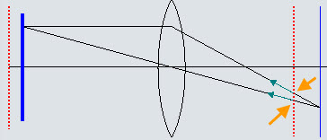
1. Start with your own diagram, but now imagine that the red lines are the sensor and in-focus plane, while the blue lines are out-of-focus planes. Question: where does the out-of-focus point image on the sensor? If only the top ray is present, then the OOF point is indicated by the top orange arrow. But if only the lower ray is present, then the OOF point is indicated by the bottom orange arrow -- a different location.

Image

2. There's a simple analogy using shadows. If you drop a flat disk on the floor and shine a light on it, the shadow remains directly under the disk no matter which direction the light comes from. That's equivalent to in-focus detail. But if you raise the disk above the floor and shine a light on it, the shadow both gets fuzzy and moves around to track the light. That's equivalent to out-of-focus detail.

3. Read carefully Theory of the “No-Parallax” Point, pages 3-6, "Ray Tracing a Thin Lens". The section closes with a brief summary: The unstopped lens would collect rays representing many different centers of perspective. The aperture selects a subset of those, and the effective center of perspective belongs to the rays that were selected. In that article, the discussion is about selecting rays by using an aperture. But the geometry is the same if the ray selection is done by shining directional light off shiny surfaces. Just as in the article, in-focus details remain in a fixed position on the sensor independent of the direction of incoming light, while the blur circles of out-of-focus details move around depending on what direction the light is coming from (subject-to-aperture).

To see the effect, it's critical that the incoming light is highly directional so that it does not fill the aperture of the lens. This condition is satisfied by a locally smooth reflector combined with a small light source and a wide aperture lens.

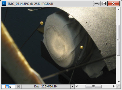
Here is a photograph of the light pattern from the dime as it enters the front of the Mitutoyo in my setup with no diffusion. I think it's clear that although the Mitty has a maximum aperture of NA 0.14, its effective aperture will be a lot less with this particular illumination. Bear in mind that what we're seeing here is light reflecting from the entire dime. The light reflecting from any small area of the dime would be much more highly localized as it enters the objective.

Image
enricosavazzi wrote:
ChrisR wrote:...
What initially looks like detail in the area outside the diffused-light in-focus band could just be small sized, high contrast, constructive interference rubbish.
...
That could be the explanation. If we know that the particular subject area is out of focus, any detail that appears in focus in that area should be an artifact, caused by diffraction and/or interference, or by the sensor-to-final-image processing chain. Or by lensing.
All those things are probably true, but they're not the whole story.

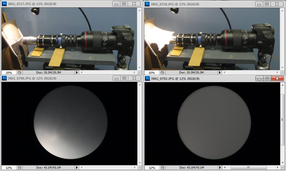
Here are photos of the scale and dime, everything the same in each pair except that on the left the lamp was bare, and on the right there was tissue paper spread over the subject.

Image

Image

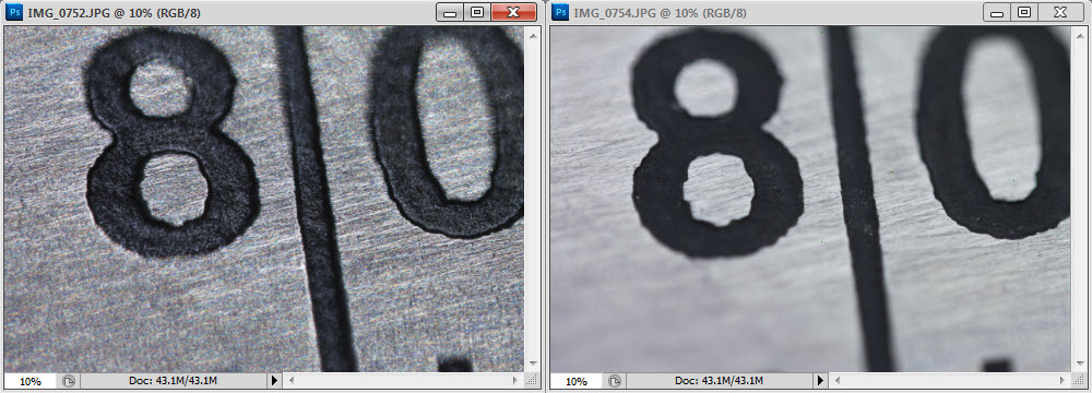
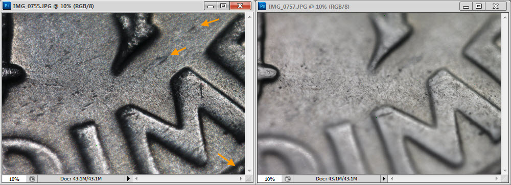
An argument can certainly be made that for the scale, all of the apparent added detail in the OOF areas is really rubbish.

But for the dime, I don't buy that argument. Take a look at the details indicated by the arrows.

No elaborate theories are needed to explain this result. All we need is the effective stopping of the aperture courtesy near-planar reflection of a small light source, as discussed above.

--Rik

rjlittlefield
Site Admin
Posts: 23598
Joined: Tue Aug 01, 2006 8:34 am
Location: Richland, Washington State, USA
Contact:

Post by rjlittlefield »

By the way, let me explain that I did not initially intend this investigation to have anything at all to do with DOF.

Instead, I just wanted to talk about the pretty colors and what might be causing them.

So I hauled out a couple of subjects that I knew from previous experience would make nice illustrations. I mounted them up, illuminated them to get a well lit result, and shot the pictures.

The colors were very nice, as expected.

But my jaw dropped when I saw the effect on DOF, because I completely was not expecting that. So in the spirit of "let's talk about unexpected effects", I threw in the DOF aspect also.

Personally I'm not very interested in the DOF aspect because I think that's well explained as effectively stopping down the aperture, as discussed above.

If you have any continuing doubts that the DOF increase is real with the dime, perhaps this animated presentation of the diffused & undiffused cases will change your mind.

Image

It's worth mentioning, once again, that there's no free lunch. While using highly directional illumination gives more DOF in this special case, it does that by effectively stopping down the lens, which increases diffraction effects to go along with the change in DOF.

--Rik

Pau
Site Admin
Posts: 6064
Joined: Wed Jan 20, 2010 8:57 am
Location: Valencia, Spain

Post by Pau »

Rik, do you allow me to post a reprocessed image?
Pau

rjlittlefield
Site Admin
Posts: 23598
Joined: Tue Aug 01, 2006 8:34 am
Location: Richland, Washington State, USA
Contact:

Post by rjlittlefield »

Sure!

--Rik

Pau
Site Admin
Posts: 6064
Joined: Wed Jan 20, 2010 8:57 am
Location: Valencia, Spain

Post by Pau »

If anyone can explain me how to find the objective rear focal plane in a microscope with a phase telescope, I may try to take pictures of it in a similar situation (plan apo 4X 0.14 objective, a coin and a LED lamp).

If it works, this may be interesting to test the stopping down objective hypothesis.
Pau

Pau
Site Admin
Posts: 6064
Joined: Wed Jan 20, 2010 8:57 am
Location: Valencia, Spain

Post by Pau »

As originally presented the left image seems more detailed, but if it's stopped down, this can't be true.
Sharpness impression, and even just visibility, in microscopy is a tradeof of resolution and contrast, and the last is very different in both images.
I've reprocessed the right image (levels and saturation) to match as possible the contrast of the left one.
Image

Now to me is much clearer that Rik is right: less DOF and smaller details resolved
Pau

rjlittlefield
Site Admin
Posts: 23598
Joined: Tue Aug 01, 2006 8:34 am
Location: Richland, Washington State, USA
Contact:

Post by rjlittlefield »

Pau wrote: If anyone can explain me how to find the objective rear focal plane in a microscope with a phase telescope, I may try to take pictures of it in a similar situation (plan apo 4X 0.14 objective, a coin and a LED lamp).

If it works, this may be interesting to test the stopping down objective hypothesis.
Beats me -- I don't have a phase telescope.

I do however have a macro lens. Here's the way it sees the rear of the objective. No diffusion on the left, maximum diffusion on the right.

Image

--Rik

ChrisR
Site Admin
Posts: 8671
Joined: Sat Mar 14, 2009 3:58 am
Location: Near London, UK

Post by ChrisR »

Right. Thanks for the explanation Rik.
While you were penning that I'd put a 100mm FL f/2 thinnish lens on the front of some extension tubes. Then punched a 5mm hole through a piece of card, put it flat to the lens and slid it around sideways. Result is, illuminatingly, the changing perspective, which is now "obviously to be expected". To restate what I mean, as the hole was moved about, the direction I was seeing my subject from was altering, so the image of it rolled about, on the sensor. As the aperture was quite small, it was pretty well all in focus.

If I might paraphrase, we get increased DOF from harder light because it’s directional, so more of the reflected image-forming light is coming through a restricted area of the lens. Like I would have seen if I’d used, instead of the card, a semi-transparent piece of film with a clear patch.

So if we have a subject where light is coming of it with a strong "direction" property, it will be going through a restricted part of the objectve. If there are different components on the subject sending their light through different parts of the objective, then we should expect the images of each part to move about laterally as we focus in and out. The smaller and stronger those directionalities are, then the smaller the effective aperture for them, so the more "in-focus" they’ll be, relative to the remaining oof part of the image.
If a 3D subject say has flat faced ridges on it (like a metal file) and we’re looking down from above, we might expect light to be coming off the faces predominantly normal (at right angles) to those faces. So as we focus, the ridges’ faces will appear to move in two different directions, because their light is coming through separated parts of the objective. This could explain what’s happenning in the image of Rik’s bug. I’m trying to decide if the movements tie up with slopes. I think they might.

Also, if the directional light is coming from some “lensing” effect, then it could be expected to be full of chromatic variation (coloured sparkles). If the structure of the surface is directional (as in a machined or crystalline surface, or organic growth) we could expect the sparkles to follow the structure. If they all “shine” off towards one part of the objective, then that lot will move one way during focusing. There could be more than one set of features, producing movements in different directions – such as in Rik’s demo.
I can only image what tiny features could cause the lensing effects. The flashs of coloured light seen from a diffraction grating, and the like, are compelling.

I'm sure If I'd slept on this I'd have carved it about. Feel free to carve for me!

CaptainFwiffo
Posts: 54
Joined: Sun Jul 29, 2012 10:45 am

Post by CaptainFwiffo »

Like Ray, I've dealt with this issue with coin photography. I've known for a while that it wasn't a sensor thing, because I can see it on some coins with my naked eyes, sometimes even without magnification.

There's one coin in-particular that has caused all sorts of nightmares for me. In-hand, it has what appears to be a proof-like finish (mirror-like), but with a strange "sparkle". Under magnification, it's revealed to be covered in very fine die polishing lines. When illuminated by a point-like light source like those Jansjo LED lights, it has the rainbow effect.

Image
1944-D Mercury Dime (reverse) by CaptainFwiffo, on Flickr
Image
1944-D Mercury Dime (reverse) by CaptainFwiffo, on Flickr

All the fine lines create other problems. It exaggerates longitudinal chromatic aberration. You can see it's not quite flat to the camera, although the DOF is sufficient to make the whole coin appear in focus. Points just behind the focal plane are greenish, while those in front are magenta. (I over-saturated the right side of the image to make the effect more visible):
Image
1944-D Mercury Dime (reverse) by CaptainFwiffo, on Flickr

And if that wasn't enough, it also suffers from the gamma resizing bug. It becomes noticeably darker when scaled down by any software that doesn't correct for gamma.

Post Reply Previous topicNext topic