Voice Coil Rail
Moderators: rjlittlefield, ChrisR, Chris S., Pau
-
Smokedaddy
- Posts: 1961
- Joined: Sat Oct 07, 2006 10:16 am
- Location: Bigfork, Montana
- Contact:
Mike, the whole circuit is more or less resistive circuit [edit] and DC[/edit] , therefore, a variable voltage source can be thought as variable current source. LM317 can give you rather stable voltage under heavy load. From ray_parkhust's data, current drawn is very small, say, under 300ma, LM317 can handle this without any issue and current flowing through the speaker will be proportional to Vout in my circuit.
Last edited by mjkzz on Sun Apr 16, 2017 10:13 am, edited 1 time in total.
Mike, of course, the digitally controlled one will be configured as current source and, again, from ray_parkhurst data, 2N2222 is probably good enough and using a current sensing resistor. The circuit is almost like yours, but the feed back is from that sensing resistor. PCB is being made now, will get it in about a week.
-
rjlittlefield

- Site Admin
- Posts: 23596
- Joined: Tue Aug 01, 2006 8:34 am
- Location: Richland, Washington State, USA
- Contact:
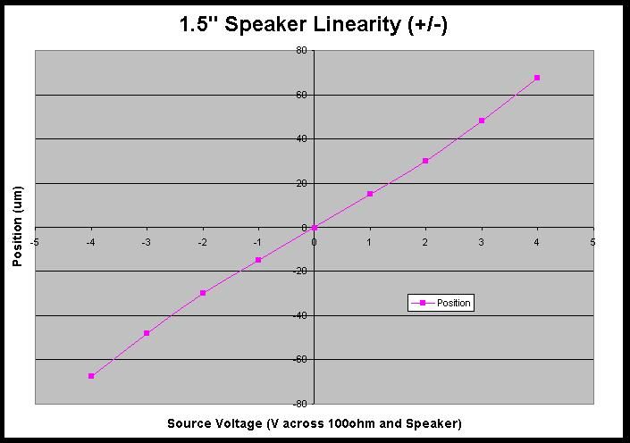
At http://www.photomacrography.net/forum/v ... 040#210040, the slight nonlinearity is in an interesting direction.ray_parkhurst wrote:Also shown below is the curve up to 7V/130um displacement, showing good linearity in that range.
It looks like the speaker cone becomes less stiff with increasing displacement, so that the same change in voltage/current results in larger moves at larger displacements.
From the graphs, I get that the slope at 7V is about 1.5X of what it is between 0 and 1V. (I measure the angles as 39 and 28 degrees, respectively, then tan(39°)/tan(28°)=1.52 .)
Based on nothing but intuition, I would have expected it to go the other way, more stiff with increasing displacement.
--Rik
-
ray_parkhurst
- Posts: 3431
- Joined: Sat Nov 20, 2010 10:40 am
- Location: Santa Clara, CA, USA
- Contact:
My video connection was a bit choppy, but that's what it looked like for me at 20x as well. For me I saw zero lateral movement, and I could move the stage across full range (or any small increment) quickly and without vibration. I was using a telecentric lens as well so no scale changes. Seems an ideal stage for stacking at high magnification or over small ranges.
At this point I see no advantage to using a purpose-built voltage or current source. I have the power supply available with variable voltage in fine increments, so will stick with it until a more advanced configuration is available. By "more advanced" I mean one that could integrate with an automated stacking system.
I suppose a simple way to integrate this concept with existing stepper-based stackers would be to build a stepper-driven potentiometer that drives the voltage or current control hardware. Seems fairly straightforward, so much so that I may be able to do it myself!
-
ray_parkhurst
- Posts: 3431
- Joined: Sat Nov 20, 2010 10:40 am
- Location: Santa Clara, CA, USA
- Contact:
The stiffness is for sure not decreasing with increased displacement. The suspension is acting as a true spring. What is happening is the magnetics are slightly over-compensating the increase in spring constant. Speaker design is a balancing act between winding densities, magnet gaps, and spring constants (among more than 10 other variables).rjlittlefield wrote:ray_parkhurst wrote: It looks like the speaker cone becomes less stiff with increasing displacement, so that the same change in voltage/current results in larger moves at larger displacements.
From the graphs, I get that the slope at 7V is about 1.5X of what it is between 0 and 1V. (I measure the angles as 39 and 28 degrees, respectively, then tan(39°)/tan(28°)=1.52 .)
Based on nothing but intuition, I would have expected it to go the other way, more stiff with increasing displacement.
--Rik
-
rjlittlefield
- Site Admin
- Posts: 23596
- Joined: Tue Aug 01, 2006 8:34 am
- Location: Richland, Washington State, USA
- Contact:
Maybe, but I think we don't have enough data to know for sure what all factors are in play. What I should have said is that the whole system seems to be getting looser with increasing displacement.ray_parkhurst wrote:The stiffness is for sure not decreasing with increased displacement. The suspension is acting as a true spring. What is happening is the magnetics are slightly over-compensating the increase in spring constant.
Or perhaps even that much is not correct. Now it occurs to me to wonder if these graphs are measured from the speaker's natural equilibrium, or if they're starting from a displaced position due to weighting with a coin et.al., so that increasing voltage is actually bringing the speaker closer to its unweighted position.
--Rik
-
ray_parkhurst
- Posts: 3431
- Joined: Sat Nov 20, 2010 10:40 am
- Location: Santa Clara, CA, USA
- Contact:
A coin and small stage was in place for the measurements. Also, my data has an offset to it...I measured displacement from 100mV, not from 0, so that will skew the slopes a bit. I was not intending to do a lot of quantitative analysis on this, so was not as precise as I could have been. I will take some additional data to see if there is any asymmetry in the displacement curve around 0V.rjlittlefield wrote:Maybe, but I think we don't have enough data to know for sure what all factors are in play. What I should have said is that the whole system seems to be getting looser with increasing displacement.ray_parkhurst wrote:The stiffness is for sure not decreasing with increased displacement. The suspension is acting as a true spring. What is happening is the magnetics are slightly over-compensating the increase in spring constant.
Or perhaps even that much is not correct. Now it occurs to me to wonder if these graphs are measured from the speaker's natural equilibrium, or if they're starting from a displaced position due to weighting with a coin et.al., so that increasing voltage is actually bringing the speaker closer to its unweighted position.
--Rik
edited to add:
Using 0V as reference, and taking data at 1V steps, I see perfect symmetry in the speaker displacement for +/- displacements. My stepper has 1.25um microsteps, and with 1V displacing only 12 microsteps, the physical linearity and repeatability of the stepper is likely contributing to the small-displacement linearity issues in my first data set. Here is the measured result with 1V steps in + and - directions:
edited to add: this data is with a small stage and coin in place, same as previous
For this data, I just swapped the polarity of my power supply to get the +/- data. To get 0V, I turned the power supply off, since the supply would not go to exactly 0V when on.
I suppose I could shift to a microscope stage if needed to measure the region around 0V accurately. That may be needed if I end up using a dual-power supply to get +/- Voltages to double the linear displacement range of the speaker.

Ray,ray_parkhurst wrote:My video connection was a bit choppy, but that's what it looked like for me at 20x as well. For me I saw zero lateral movement, and I could move the stage across full range (or any small increment) quickly and without vibration. I was using a telecentric lens as well so no scale changes. Seems an ideal stage for stacking at high magnification or over small ranges.
At this point I see no advantage to using a purpose-built voltage or current source. I have the power supply available with variable voltage in fine increments, so will stick with it until a more advanced configuration is available. By "more advanced" I mean one that could integrate with an automated stacking system.
I suppose a simple way to integrate this concept with existing stepper-based stackers would be to build a stepper-driven potentiometer that drives the voltage or current control hardware. Seems fairly straightforward, so much so that I may be able to do it myself!
Think Peter indicated he's got a circuit board coming with a DAC (Digital to Analog Converter) that's configured as a current source Voice Coil Driver. This is for direct computer control.
With this configuration it should be easy to automate the Voice Coil and stacking setup, allowing very quick stacks.
This setup should allow the ability to "pre-distort" the DAC control and compensate for the Voice Coil non-linearity, a simple look up table is all that's required. Digital Pre-Distortion is something that's very common today with digital control, it's even used in your cell phone for improving RF transmitter linearity.
Best,
Mike
Peter,mjkzz wrote:Mike, of course, the digitally controlled one will be configured as current source and, again, from ray_parkhurst data, 2N2222 is probably good enough and using a current sensing resistor. The circuit is almost like yours, but the feed back is from that sensing resistor. PCB is being made now, will get it in about a week.
Here's Bi-directional current source that is simple and cheap. Replace the voltage reference and Pot with a DAC and you have full digital control. Like I mentioned to Ray, with digital controlled sources you can do digital Pre-Distortion to improve Voice Coil position linearity.
With a 12 bit DAC you can achieve 1 part in 4095 resolution which would allow you to drive the voice coil well into it's non-linear region and correct with pre-distortion.
Best,
Mike

OK, Mike, thanks for the circuit.
Do you think that non-linearity is due to the coil? I think it is due to the construction of speaker where the "spring" (speaker cone) is not linear.
I do not know the term "pre-distortion", but a look up table can correct/make it linear. But the best solution is to make it a closed loop system, so a linear encoder as feedback is better solution, but will be far expensive.
Anyways, one day I will plot a graph of V and I for the variable voltage with speaker as load. I expect a straight line as I think it is linear or close to as long as you do not change the POT really fast so the whole circuit is DC and the speaker is just another resistor (in my case a 4-ohm coil)
I have a BEI voice coil motor coming from junk yard, it has a few mm stroke, hopefully it is working one, then we can get rid of that speaker thing :-)
Peter,mjkzz wrote:OK, Mike, thanks for the circuit.
Do you think that non-linearity is due to the coil? I think it is due to the construction of speaker where the "spring" (speaker cone) is not linear.
I do not know the term "pre-distortion", but a look up table can correct/make it linear. But the best solution is to make it a closed loop system, so a linear encoder as feedback is better solution, but will be far expensive.
Anyways, one day I will plot a graph of V and I for the variable voltage with speaker as load. I expect a straight line as I think it is linear or close to as long as you do not change the POT really fast so the whole circuit is DC and the speaker is just another resistor (in my case a 4-ohm coil)
I have a BEI voice coil motor coming from junk yard, it has a few mm stroke, hopefully it is working one, then we can get rid of that speaker thing :-)
The non-linearity is probably a combination of things but mostly the cone I suspect. In any case it's relatively easy to correct with digital controls. I'm sure your BEI motor will work better.
Certainly a closed loop system is preferred but as you mentioned more complex and expensive. The system we did back in 1980 had both, we used a Laser (HeNeon) for the encoder for feedback in closed loop and digital pre distortion for open loop correction, this was necessary because the "loop" could lock onto the wrong laser cycle without pre distortion (system open loop absolute position error was greater than HeNeon wavelength). When the loop was closed the position error was a very small fraction of HeNeon wavelength.
I would think a larger speaker such as a 8, 10 or even 12" woofer would have better near zero displacement linearity, better load support and longer displacement than a smaller one. Drawback would be larger driver current, but that's easy to solve.
BTW just a thought on the DAC control. If you have a small micro controller setup with a couple 8 bit DAC outputs (which I suspect what you are doing), then using both DAC outputs can be beneficial. Use one as the "Coarse" DAC control and the other as the "Fine" control by combining them. If you combine them with a 100 to 1 scale factor (simple resistive), then the fine will have a 2.5 LSB bit overlap, or use a 256 to 1 and have a 1 LSB range, in this case you have 256 Fine micro-steps per LSB Coarse Step!!
Wish I had time to actually build some things along these lines, but I'll leave that to you and Ray.
Best,
Mike
Peter, Ray,
Another source for a Voice Coil actuator rather than a speaker is the actuator for the RW heads on a hard drive. These may have too large a displacement for our direct imaging applications though.
However I'm thinking of using one to rotate the subject since you can see about 45 degrees rotation from these YouTube videos.
https://www.youtube.com/watch?v=NQfAPciPwZY
https://www.youtube.com/watch?v=OfMfUTHl4R8
Best,
Mike
-
ray_parkhurst
- Posts: 3431
- Joined: Sat Nov 20, 2010 10:40 am
- Location: Santa Clara, CA, USA
- Contact:
The nonlinearity is for sure a combination of things. Speaker voice coils are designed to have nonlinear force vs displacement to correct the suspension nonlinearities. This can only be used to a certain displacement...the suspension eventually wins.mawyatt wrote:...The non-linearity is probably a combination of things but mostly the cone I suspect. In any case it's relatively easy to correct with digital controls. I'm sure your BEI motor will work better.
...
I would think a larger speaker such as a 8, 10 or even 12" woofer would have better near zero displacement linearity, better load support and longer displacement than a smaller one. Drawback would be larger driver current, but that's easy to solve.
I would think a smaller, large displacement woofer would be the best for this application. Smaller woofers are designed to have larger displacements with good linearity. Big woofers don't have to move as much for the same SPL.
I am a bit worried about the crossover distortion of the op amp circuit shown. Input offset may cause a fair bit of nonlinearity near equilibrium point.
OK, it seems we are speaking of different things :-). I am talking about circuit, under DC circuit, a speaker is just like another resistor, so a variable voltage source can be thought as current source.The non-linearity is probably a combination of things but mostly the cone I suspect. In any case it's relatively easy to correct with digital controls. I'm sure your BEI motor will work better.
I think you and ray_parkhurst are talking about final output, which is rightly so, it definitely not linear. Beside my junk BEI motor, why can't we remove the speaker cone and replace it with some sort of spring with linearity, I mean for 2mm displacement, it ought be easy to do :-)