OM Variable macro tube

Have questions about the equipment used for macro- or micro- photography? Post those questions in this forum.

Moderators: rjlittlefield, ChrisR, Chris S., Pau

augusthouse
Posts: 1195
Joined: Sat Sep 16, 2006 1:39 am
Location: New South Wales Australia

OM Variable macro tube

Post by augusthouse »

This looks useful. Is anyone using or had experience with one of these. Being an OM it has to be good.

It's an Olympus OM Variable Macro Tube.

Image
Image
Image


Especially if you put one of these on the end?
Image

I'm sort of glad I don't yet have an OM catalogue - I'd want just about everything it it.

rjlittlefield
Site Admin
Posts: 23621
Joined: Tue Aug 01, 2006 8:34 am
Location: Richland, Washington State, USA
Contact:

Post by rjlittlefield »

Craig,

I've never worked with either of those devices, but...

Regarding the Variable Macro Tube, see technical description at http://www.alanwood.net/photography/oly ... -tube.html .

In summary...
Compared with the Auto Bellows, it has a longer minimum extension (65 mm instead of 36 mm) and shorter maximum extension (116 mm compared with 198 mm), but its metal construction makes it stronger then the leather bellows, and it provides an automatic diaphragm without needing a double cable release.
Used in conjunction with an OM body that has the proper auto diaphragm coupling, the Variable Macro Tube will allow the Olympus auto bellows macro lenses to be easily used in the field, including hand-held. Used with any other body, it will be rather less helpful since (as far as I know) it provides no means to stop down the lens and keep it stopped down.

Regarding the third picture, see http://www.alanwood.net/photography/oly ... ctors.html . This is a Lieberkühn reflector. Its intended purpose is to reflect light coming from behind the subject onto the front of the subject. A very handy device in some setups, but I'm not sure how many.

BTW, the catalog you want can be found at http://www.alanwood.net/photography/olympus/ . It lists all that cool stuff that Olympus made for macro.

--Rik

DaveW
Posts: 1702
Joined: Fri Aug 04, 2006 4:29 am
Location: Nottingham, UK

Post by DaveW »

"This is a Lieberkühn reflector. Its intended purpose is to reflect light coming from behind the subject onto the front of the subject."

Oxford Scientific Films, who used to do a lot of "cutting edge" natural history photography on British TV, constructed a special parabolic reflector for the lenses on their optical bench for this purpose I remember reading.

DaveW

augusthouse
Posts: 1195
Joined: Sat Sep 16, 2006 1:39 am
Location: New South Wales Australia

Mirror Housing

Post by augusthouse »

Hi,
Now I understand how the Lieberkühn reflector works in principal. It's for shadowless lighting. When illuminating from below it catches any stray light and bounces it back down onto the subject.

I'm trying to find a mirror housing like the B&W picture attached. Not getting much joy on eBay. Should I be using a different search criteria? I've been searching for 'mirror housings'

I know what the item in the picture is and basically how it works. It is from the Olympus catalogue link you sent through Rik.

I'm attempting to emulate the mirror housing aspect it in an affordable way. Needs to be about 2 inches long by 2 inches wide.

It won't be attached to the lens as in Diagram 1. I haven't worked out what's going on there yet. * Later note - I have now and will have to put that on the list of things to do.

For my little project it's being used in a vertical stack setup. On top of a Newport 260A right angle Z fitting that is controlled by a micrometer I have a 2" by 2" xy positioning stage. The mirror housing will sit on this. (See diagram 2 &3 below.)

I'm trying to build a setup similar to the Olympus PMT-35; but in my case it will involve a physical separation from the camera support and the subject stage. The subject stage is attached to a Durst enlarger stand and with the Newport and friends forms a stacking bench. The camera and bellows are attached separately to a Nikon PF-4 Repro/Copy stand.

Diagram1.
Image

Diagram2.
Image

Diagram3.
Image


Mirror housing.
Image

Craig
Last edited by augusthouse on Sat Jul 28, 2007 4:40 pm, edited 2 times in total.

rjlittlefield
Site Admin
Posts: 23621
Joined: Tue Aug 01, 2006 8:34 am
Location: Richland, Washington State, USA
Contact:

Post by rjlittlefield »

I've never looked for one of these, so I have no idea how often they come up.

As for an affordable substitute, try using an ordinary piece of glass instead of that fancy beam splitter. In low power microscopy, it's traditional to use a cover slip mounted at 45 degrees to the surface. Shine light in from the side, most of it goes straight through but some reflects down onto the subject. The lens looks straight down as usual, so it's looking through the tipped cover slip. The big trick is to be sure that there's only very black stuff on the far side of the cover slip from the light source, since the imaging lens will see that area overlaid on the subject. It'll be completely OOF, of course, but any light will still cut into your contrast.

--Rik

augusthouse
Posts: 1195
Joined: Sat Sep 16, 2006 1:39 am
Location: New South Wales Australia

Edited post

Post by augusthouse »

Hi Rik, I was in the middle of editing my earlier post when you were uploading a response to it.

The Olympus PM35 in all its glory. This is not mine - I wish...

Image

Thinking vertically - It's the back lighting I'm after as well. Below are some details regarding the Mirror Housing.

"These Mirror Housings are easily clamped onto the 80mm, 38mm or 20mm Macro Lens (both the Manual versions and the Automatic versions).
A transparent angle mirror reflects horizontal entering incident light vertically onto the subject"

I don't need to 'clamp' it to the lens' as in Diagram 1 in earlier post.

Just trying to nut together the components and what they are doing.

Isn't this basically what an illuminator in the base of a microscope stand and the condenser assembly does in regards to light?

I don't have the experience or background that you guys have, so for me at times it's a bit of a 'mechano or lego' construction excercise. I recognize the components I need; but I don't always know what they are actually called.

So the mirror is actually a beam splitter and the box is its house?

As this assembly is under the subject as in Diagram2 and Diagram3 of earlier post, could I use a mirror or ideally a prism like photo below. The prism would be housed in a box which has a large opening at the top and one in the side for the light source to enter. The subject would be positioned over the opening at the top.

Image


Craig
Last edited by augusthouse on Sat Jul 28, 2007 3:01 pm, edited 3 times in total.

augusthouse
Posts: 1195
Joined: Sat Sep 16, 2006 1:39 am
Location: New South Wales Australia

Just to clarify

Post by augusthouse »

Just to clarify.

I'm building a setup which works in the same way as a microscope but uses a camera and bellows (and a selection of lens options) instead of an eyepiece.

The vertical subject stage is built using components that allow for sufficient, measured fine focus travel necessary for stacking and positioning.

Like a microscope it allows for back lighting (filters if required). I will also be using fiber optic lights from overhead (epi I believe this is called) and a diffuser that should also serve in some measure as a Lieberkühn reflector for the light coming up through the 'mirror housing'.

Craig

DaveW
Posts: 1702
Joined: Fri Aug 04, 2006 4:29 am
Location: Nottingham, UK

Post by DaveW »

For a mirror to be a beam-splitter you need a semi-silvered mirror for that, not an ordinary one and any mirrors need to be surface silvered to avoid double reflections. The mirror on a DSLR or SLR is surface silvered. That is the silvering is on its face not it's back or you get a slight reflection off the glass front surface and one of the back silvering, meaning when they are angled at forty five degrees you would get a double reflection in the viewfinder. Some are also semi silvered to act as a beam splitter to allow light through to the metering sensor which is why you cannot use linear polarisers with most of today's DSLR's but need a circular polariser.

I would have thought you would be able to get semi-silvered mirrors or beam splitters by "Googling" around. For instance here, but hopefully not as expensive as these!:-

http://www.thorlabs.com/Navigation.cfm? ... 0splitters

DaveW

augusthouse
Posts: 1195
Joined: Sat Sep 16, 2006 1:39 am
Location: New South Wales Australia

Post by augusthouse »

Thanks Dave W. Appreciated.

I'll take the information you provided onboard.

I was thinking that the opening on top of the 'mirror housing' might also need a diaphram and or condenser; but I'm thinking that a diffuser in the stage plate and a filter holder of some description would do the job considering the intended use.

The 'mirror housing' is just a desired add on. The rest of the setup is working well. Still have some parts in transit; but I'm having a ball building this and it hasn't cost a fortune.

* Later note: I managed to find a copy of the manual for PMT-35 and I have a bit more info regarding it's components. So I will have a good look through.

Craig

augusthouse
Posts: 1195
Joined: Sat Sep 16, 2006 1:39 am
Location: New South Wales Australia

Dave W

Post by augusthouse »

Hi DaveW,
You mentioned once before that you also use a Durst M601 enlarger base. Do you still have the head of that enlarger? I do. Inside there is a 'mirror housing' that it is just the size I need (3" x 3") and some other parts - including filters that complete the component.

The little 'sivobox' that sits on top of the 'mirror housing' is also a beautiful thing (mirror lined box - no base - diffuser on top), both of which are the weight of 2 match boxes.

If you still have the M601 head can you have a look at the 'mirror' and tell me what you think with respect to your earlier input regarding the actual mirror component and my intended use as indicated in Diagram 2 and 3 in an earlier post in this thread. Thanks.

I'm going to do some searching and reading regarding Mr/Mrs Lieberkühn after I buy some ping pong balls - for starters and something smaller? for the microscope objective. Currently testing with a (seen better days) 2.5 Carl Zeiss 160/-

Keeping in mind that this is a vertical stacking bench that I'm building, the increments of which are controlled by a micrometer.

By gently immersing the subject in light from below and above, for example butterfly wings or insect heads there are facets in those subjects which are interacting with the light in surprisingly unexpected ways - bit like the red light in your Click beetle post Rik. It's like having a Christmas tree and then suddenly turning on the lights. I don't think you would see these facets by just illuminating or 'flooding' the subject with light. I wonder how a flash would go here?
Here is some interesting reading.

http://www.alanwood.net/photography/oly ... ctors.html

Craig

rjlittlefield
Site Admin
Posts: 23621
Joined: Tue Aug 01, 2006 8:34 am
Location: Richland, Washington State, USA
Contact:

Post by rjlittlefield »

Craig,

Welcome to the wonderful world of lighting!

Following are a couple of schematic diagrams of how you might expect the mirror illumination systems to work.

The first scheme uses a thin slab of glass -- like a microscope slide or cover slip. Notice that there's a faint double image due to multiple reflections, but essentially no color fringing. This is the same amount and type of distortion that you see in looking obliquely through a single pane of window glass.

Image

The second scheme tries to swap in a prism in place of the thin slab. At first glance it's attractive because you're looking straight into glass surfaces. However, the overall imaging path goes through a strong prism and it would be surprising if you did not get strong color fringing as a result. Actually, it would be a bit surprising if it worked at all. These 45-degree prisms are typically intended to serve as "first surface"mirrors by exploiting 100% internal reflection off the slanted surface -- see http://www.jmloptical.com/level2/Produc ... _info.aspx . So most likely, you won't get anything useful along the "imaging path" at all!

Image

Note that the many forms of light tents are not vulnerable to any of these problems. Light just goes from the tent to the subject and from there to the imaging lens. If you need to look straight down a deep hole, then obviously you need a vertical illuminator. But for most macro subjects, I suspect you'll find that a pingpong ball, or a whiffle ball, or a simple paper tent is a lot easier to set up and produces excellent results.

The proof of the pudding is in the pictures, of course. What kinds of pictures are you getting?

--Rik

Edit: Fixed the second picture to show more correctly (but still approximately) how the light would be reflected & refracted. Previous version had the wrong direction of bending at top and right surfaces of the prism.
Last edited by rjlittlefield on Sun Jul 29, 2007 3:14 pm, edited 1 time in total.

DaveW
Posts: 1702
Joined: Fri Aug 04, 2006 4:29 am
Location: Nottingham, UK

Post by DaveW »

Not looked inside the enlarger yet. However as it is only to redirect the light I would have thought any mirror in an enlarger would be a normal one. I will have to have a look.

As Rik's diagram shows you only need a beam splitter or semi-silvered mirror if you are looking directly through it and lighting from the front. In Rik's illustration I would think a semi-silvered mirror would reflect more light onto the subject than a sheet of glass but may not let as much through to the camera.

A one way mirror, as used by shop security men before CCTV, is in fact a semi-silvered mirror and relies on the viewer being in the dark whilst the subject is well lit.

DaveW

rjlittlefield
Site Admin
Posts: 23621
Joined: Tue Aug 01, 2006 8:34 am
Location: Richland, Washington State, USA
Contact:

Post by rjlittlefield »

DaveW wrote:In Rik's illustration I would think a semi-silvered mirror would reflect more light onto the subject than a sheet of glass but may not let as much through to the camera.
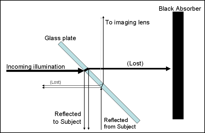
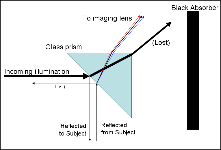
You get more net transfer of light from source to camera, by using a semi-silvered mirror. In theory, the peak happens around 50%. (Formally: f(t) = t*(1-t) reaches a maximum at t=0.5)

In practice, that bit of theory doesn't matter much because you usually have lots more light than you really need.

There's a counter argument in favor of low reflectance, based on noting that the brightness of the offset image is the product of the front surface and back surface reflectances (because that image comes from light that bounces off both). For example, a mirror that's 50% at the front surface and 5% at the rear surface will yield an offset image that is 2.5% as bright as the main image. A mirror that is 5% at both surfaces will require 10 times as much light, but will yield an offset image that's only 0.25% as bright as the main image -- an improvement of 10X.

In many cases, "best" will be some combination of convenience, availability, planarity, clarity, and cleanliness of the beamsplitter. Microscopy slides and cover slips score high on all of those counts.

--Rik

augusthouse
Posts: 1195
Joined: Sat Sep 16, 2006 1:39 am
Location: New South Wales Australia

Post by augusthouse »

I have attached a sample image. It is not a stack and it does not have any overhead lighting or diffusers on the lens - yet. I used a Carl Zeiss Plan 2.5 160/- on the bellows. Distance from the objective shoulder to the D100 sensor was approx. 170mm. The image is nothing spectacular; but it does show some interesting detail. Applied Unsharp Mask in Photoshop at 25%. Butterfly wing area in shot is approx. 5x5mm.

First indications are encouraging for what I am aiming to do and I am interested in exploring this approach, based on what I have read and its history - especially its use by Olympus. With the detailed info that you guys have provided I have more to work with now in a practical sense.

Initially, I was just after some back-lighting for background composition but quickly realised that there was a lot more science going on here that could be utilized. Now begins the learning curve and I look forward to it.

Craig


Image

Larger file (3.5mb) here.
http://www.augusthouse.com.au/images/test7.jpg

rjlittlefield
Site Admin
Posts: 23621
Joined: Tue Aug 01, 2006 8:34 am
Location: Richland, Washington State, USA
Contact:

Post by rjlittlefield »

augusthouse wrote:Initially, I was just after some back-lighting for background composition but quickly realised that there was a lot more science going on here that could be utilized. Now begins the learning curve and I look forward to it.
Ah yes, the learning curve. I spend a lot of time on that one myself.

In my setup, shown here, there's a separate tube specifically for backlighting, with its own bulb and a slot for inserting colored paper for the light to shine through.

When I built that, my thought was to mimic Charlie Krebs' scheme for using his microscope's base illuminator in conjunction with overhead lighting and a pingpong ball.

The first few times I used it, I was pretty happy. See here and here and here, for examples.

But the more I used it, the less happy I became.

The difficulty came in trying to simultaneously balance brightness and color of the back- and front-lighting. Because the bulbs are different and are on separate dimmers, their relative color balance changes dramatically depending on dimmer setting. This was not a big problem as long as I was happy with strongly colored backgrounds and didn't care exactly what that color was. But when I started trying to make more neutral backgrounds, I discovered that the device was essentially impossible to control.

So, I switched strategies.

Now, I'm much more likely to set up just a piece of colored paper as background, and light both it and the subject with the same dual fiber halogen illuminator. (See here, for example.) The halogen bulb's color shifts dramatically when I dim it too, but that's easily corrected with the camera's custom color balance since the background and the subject both see the same color light. (I just have to make sure to not touch the dimmer after I set the color balance!)

I'll be interested to see what you come up with. Keep us informed, please. :D

--Rik

Post Reply Previous topicNext topic