If you put "speckle pattern" into Google and look at "Images" you see many which demand attention, and lead to avenues of discovery.
There's nothing much new in the understanding in the last 100 years, as far as I can tell, but without specific education or having worked in the field, it's not trivial to pull together what's actually happening.
When something does appear to be insightful or particularly revealing, there will always be someone more familiar with the issues who would quite reasonably be in a position to say, "Yes, of course, standard stuff, could have told you that". [Edit - ] With hindsight that looks rather carping, perhpas at Rik. It wasn't meant to be. The "someone" is more often than not the author of a book on a related matter who deals with the much-vexed issue of the moment, in a brief paragraph.
In discussions of the phenomena illustrated and discussed in this thread, and closely related ones off the forum, it’s becoming clear that we’re staring at a number of mechanisms which interact. It becomes difficult to address one in isolation, as a result. Each is more or less obvious, but nobody to my knowledge has pulled things together very much.
I did find (in a book, not online) a treatment of the Fraunhofer diffraction patterns which showed illustrations which were compelling in their familiarity. Rather like this one from a rectangular aperture, (OR a small reflective rectangle with small/coherent illumination source) http://en.wikipedia.org/wiki/Fraunhofer ... r_aperture .
I do have a machine-shop’s surface finish comparison plate, which has samples of stainless steel, with measured "micron" finishes from very smooth, to rough enough to easily feel ridges with a fingernail. It’s fun to take it to different light sources (laser, sun(quite coherent), led..) and I daresay meaningful measurements could be made, but, don’t wait up...
False color and detail/DOF from shiny metal
Moderators: rjlittlefield, ChrisR, Chris S., Pau
I went through the thread again, and hopefully picked up most of the other contributions that covered the points I touched on. Sounds like there is good agreement among several that the "mechanical" features on the metal surface play a role in creating the spectral dispersion-like effects. Check! 
I looked at several of the referenced articles, web sites, links, etc., but not all. One topic that is still nagging at me is the idea of speckle effect with an extended source. In the process of re-reading about it, I found the definition of white light coherence in an optical system, so I will relay that.
From Goodman's "Introduction to Fourier Optics", 3rd ed, p.135, through a relationship of angular size of the source, entrance pupil and angular sprectrum of the subject, an incoherent optical system can behave mostly like a coherent system. The relation for coherence is when angular size of the source is much less than the angular size of the entrance pupil. By inverse, the system is incoherent when the angular size of the source is greater than or equal to the angular size of the entrance pupil plus the angular size of the angular spectrum of the object. All angular diameters are as measured from the object plane. "In between" cases are considered to be "partially coherent".
Since at least a couple of posters were playing with a directed source underfilling the aperture, there may be a way to connect the phenomenon of "effective aperture" (as named here) to partial coherence. Goodman doesn't cover partial coherence other than a couple brief mentions, so another source would need to be consulted. Partial coherence is definitely in the weeds as far as my own knowledge is concerned, so I have nothing anecdotal to add, unfortunately.
There is more I would like to comment on regarding speckle, but the brain is fried, so I'll leave it for another time!
-
rjlittlefield

- Site Admin
- Posts: 23626
- Joined: Tue Aug 01, 2006 8:34 am
- Location: Richland, Washington State, USA
- Contact:
Yep, context is important. I originally started this thread because in another thread colored spots on coins were getting attributed to sensor overload. I wanted some material to clear up that misconception, so I shot a few pics of my own. Obvious the thread has taken on a life of its own beyond its humble beginnings!Asha wrote:Also, I was agreeing with the poster who wrote that an absence of oxides would preclude interference due to thin film effects.
Thank you for the reference & snippet from Goodman. That one is new to me.From Goodman's "Introduction to Fourier Optics", 3rd ed, p.135,
It's reassuring to hear that narrow illumination combined with a broad aperture will behave "substantially like a coherent system". That makes my intuition happier, at least.
But I'm still bothered by the issue of coherence length. That seems difficult to nail down. In the Google search I mentioned on "coherence length white light", one of the papers that turned up is "The coherence length of black-body radiation". At one point the paper says "For example, the coherence lengths of sunlight (T = 6 kK) and incandescent light with T = 3 kK are 0.6 µm and 1.2 µm, respectively." But later, it notes that
It's worth noting that the band-pass filter in question was nominally 560-595nm, stretching from upper green to almost red -- not nearly as narrow as I would have guessed from the numbers. Anyway, if 12 fringes implies 12 wavelengths of coherence, then it seems like we're up into big enough numbers to have quite an effect on the 50X observations (5 microns pixel size / 50X = 0.1 micron per pixel).One should bear in mind that what is observed also depends on the spectral response of the detector used. A case of practical importance is when the observation is visual. If we take the FWHM of the spectral response of the human eye as 100 THz, the coherence length lc can be calculated using equation (11)§ as 3 µm. Because the spectral response of the human eye reaches its maximum at lambda about 550 nm, lc/lambda is about 5.5. Therefore coloured fringes up to fifth order are visible [6].
As an example figure 2 shows measured intensity distributions of Newton’s rings. The fringes were generated with incandescent light and observed by a linear CCD array. Because the spectral response of the detector used was similar to that of the human eye, about five maxima occur (figure 2(a)). If the spectral bandwidth of the light is narrowed by a band-pass filter, the number of fringes increases up to twelve (figure 2(b)).
Relating to this, the dual-slit experiment that I mentioned at http://www.personal.psu.edu/ref7/appara ... -DA-LC.htm is a straightforward experimental report with an abstract as follows: "The short coherence length of white light is demonstrated by showing how the insertion of a microscope slide over one of a pair of slits removes the two-slit interference pattern. The coherence length can be estimated by covering each slit with a separate cover glass, and bending one glass away from its slit until the interference pattern disappears."
What's not mentioned in the abstract is what I thought was the highlight of the paper. That's the result: "Our observation is that the interference pattern disappears when q is somewhere between 20 and 30 degrees. This corresponds to an upper limit of 25 wavelengths or so for the coherence length, which is surprisingly large compared to the accepted value of a few wavelengths."
Unfortunately, I no longer trust the "25 wavelengths" number. On carefully reading & contemplation I find that: a) the cover glass was only 0.16 mm thickness (roughly 300 wavelengths); b) the formula used to calculate the numbers is not shown (apparently it died in conversion to HTML); and c) when I independently calculate the ray paths and optical path lengths with 20-30 degree tilt, I get much smaller differences, on the order of 1/2 wavelength. So I now consider it an open question what if anything that paper actually means.
I'll be interested to hear further comments about speckle, when your brain becomes unfried.
--Rik
Asha, welcome to the forum!
Over the past few weeks, I've been "playing with" (good term--it's way too much fun to be called "work") a directed light source and underfilled aperture. It's interesting stuff. "Fate willing and the creek don't rise," sooner or later there will be a forum thread coming out of this play. I think the concept of utilized aperture has some importance in helping understand phenomena that some of us have glimpsed and perhaps been puzzled with. Since I intend to be writing about aspects of utilized aperture soon, and having "utilized aperture" remain an unambiguous (if obscure) term will help keep things straightforward, I'd hope to avoid creating confusion about its use.
Cheers (and I have a sense that you will prove a strong contributor to this forum),
--Chris S (as distinct from Chris R )
)
I suspect you meant to type "utilized aperture"? As we know, "effective aperture" is a long-established term with a different usage.Asha wrote:Since at least a couple of posters were playing with a directed source underfilling the aperture, there may be a way to connect the phenomenon of "effective aperture" (as named here) to partial coherence.
Over the past few weeks, I've been "playing with" (good term--it's way too much fun to be called "work") a directed light source and underfilled aperture. It's interesting stuff. "Fate willing and the creek don't rise," sooner or later there will be a forum thread coming out of this play. I think the concept of utilized aperture has some importance in helping understand phenomena that some of us have glimpsed and perhaps been puzzled with. Since I intend to be writing about aspects of utilized aperture soon, and having "utilized aperture" remain an unambiguous (if obscure) term will help keep things straightforward, I'd hope to avoid creating confusion about its use.
Cheers (and I have a sense that you will prove a strong contributor to this forum),
--Chris S (as distinct from Chris R
Goodman, Statistical Optics, P323 - several pages.Goodman doesn't cover partial coherence other than a couple brief mentions
http://cdn.preterhuman.net/texts/scienc ... oodman.pdf
ChrisS--Thanks and yes, "utilized aperture". As I said, my brain was fried. This morning my excuse is that I'm still waking up, lol.
ChrisR--Thanks for that. It is the reference cited for further reading from Goodman's Fourier Optics. Still, only several pages? How about a thesis?
Rik--some quick thoughts. I observed white light fringes on an interferometer. They are very faint due to construtive/desstructive combination of all the spectral fringes. An interferometer usually displays the most visibly discernable fringes at a sub-wavelength optical path differences. I'm not saying this necessarily proves or negates the other paper, but to me it raises the same questions you have about how valid the cover slide method would be.
Regarding spectral response--I assume this is already understood, but I'll restate it anyway for the purposes of background info: 6000K and 3000K are the approximate peak spectral responses for sunlight and an incandescent bulb, respectively. The "peak" is in the Planck blackbody curve. Visible light is a narrow sliver of that curve, so there is quite a bit of energy coming from the non-visible parts of the spectrum. That is one reason a band-pass filter would be needed: if the detector spectral response is capable of seeing the energy that our eye can't, and if we don't want that energy, it needs to be blocked. Chances are that the detector and band-pass filter also have anti reflection coatings, which have their own spectral response (fortunately, it tends to be relatively constant in the regimes of interest, assuming the ARC was designed correctly).
Intuitively, 30nm of bandpass seems small for the visible, but it is within the realm of measurement instrument capability and probably of many multi-layer coating processes as well. Regardless, it doesn't surprise me that a 30nm bandpass can show definitive increase of detail in the fringes, because there is a lot of flux being eliminated.
Edit to add: I re-read what I wrote about peak response, and it sounds confusing. 6000K and 3000K are characteristic temperatures that produce a particular response curve by using the Planck equation. The temperatures themselves are not the peak response. However, there may be parts of the spectrum of interest that are on or near the peak.
-
rjlittlefield
- Site Admin
- Posts: 23626
- Joined: Tue Aug 01, 2006 8:34 am
- Location: Richland, Washington State, USA
- Contact:
Cross-linking a couple of threads...
For some further illustration and discussion of utilized aperture as it affects the appearance of shiny subjects, see HERE.
--Rik
For some further illustration and discussion of utilized aperture as it affects the appearance of shiny subjects, see HERE.
--Rik
-
ray_parkhurst
- Posts: 3439
- Joined: Sat Nov 20, 2010 10:40 am
- Location: Santa Clara, CA, USA
- Contact:
Sorry to dredge up this old thread, but I missed most of it the first time around. It was referenced in another thread so I finally saw all the excellent responses. I think the genesis of the thread may be my fault anyway since I had earlier published the presumption that these speckles were related to sensor overload (having read that in another thread...) but this is clearly not the case. Mea Culpa.
I recently did an aperture sweep to show the effect of aperture on color and sharpness for a thread in another forum. The result was interesting and I am not sure if it was consistent with an earlier aperture sweep published in this thread. What I see is that "speckle" shows up on large apertures, but gradually reduces as the aperture decreases beyond a certain point. By the time you can see visible sharpness reduction, the speckle is gone. This seems a very different result from the aperture sweep shown earlier, where the speckle exists even at very small apertures. I used a Jansjo LED light, 105mm Printing-Nikkor, M=1:1, 100% unprocessed crops. Here are the images:
f2.8, f5.6 effective

f3.3, f6.6 effective

f4.0, f8 effective

f4.7, f9.4 effective

f5.6, f11.2 effective

f7.1, f14.2 effective

f8.0, f16 effective

To show the effect more dramatically, here are the f2.8/5.6 effective and f8.0/16 effective shots with heavy saturation enhancement:


Even at f16 effective there is only a small amount of sharpness reduction, yet the colored speckles have all but disappeared.
So is this consistent with the diffraction argument for speckles? It seems to be but it seems at odds with the previous aperture sweep results.
I recently did an aperture sweep to show the effect of aperture on color and sharpness for a thread in another forum. The result was interesting and I am not sure if it was consistent with an earlier aperture sweep published in this thread. What I see is that "speckle" shows up on large apertures, but gradually reduces as the aperture decreases beyond a certain point. By the time you can see visible sharpness reduction, the speckle is gone. This seems a very different result from the aperture sweep shown earlier, where the speckle exists even at very small apertures. I used a Jansjo LED light, 105mm Printing-Nikkor, M=1:1, 100% unprocessed crops. Here are the images:
f2.8, f5.6 effective
f3.3, f6.6 effective
f4.0, f8 effective
f4.7, f9.4 effective
f5.6, f11.2 effective
f7.1, f14.2 effective
f8.0, f16 effective
To show the effect more dramatically, here are the f2.8/5.6 effective and f8.0/16 effective shots with heavy saturation enhancement:
Even at f16 effective there is only a small amount of sharpness reduction, yet the colored speckles have all but disappeared.
So is this consistent with the diffraction argument for speckles? It seems to be but it seems at odds with the previous aperture sweep results.
-
rjlittlefield
- Site Admin
- Posts: 23626
- Joined: Tue Aug 01, 2006 8:34 am
- Location: Richland, Washington State, USA
- Contact:
I believe the reason for this difference lies in the illumination.ray_parkhurst wrote:...but it seems at odds with the previous aperture sweep results.
Consider the snippet pointed out by Asha at http://www.photomacrography.net/forum/v ... 689#126689 (several posts above here in the same thread). That snippet, summarized from Goodman, says
I assume the previous series that you're referring to is the one by michael_r at http://www.photomacrography.net/forum/v ... 061#124061 (again in this same thread, but now on the previous page). In that series, he notes that the setup used "direct illumination with jansö", while his apertures with respect to the subject went down only to about f/11.The relation for coherence is when angular size of the source is much less than the angular size of the entrance pupil. By inverse, the system is incoherent when the angular size of the source is greater than or equal to the angular size of the entrance pupil plus the angular size of the angular spectrum of the object. All angular diameters are as measured from the object plane. "In between" cases are considered to be "partially coherent".
An undiffused jansö lamp is quite a small source because despite that impressively large reflector surrounding the LED, most of the light comes directly from the LED die, which is only about 3 mm square. To make that point more vivid, here is what my camera sees when it's aimed into an undiffused jansö, and I crank down the exposure and add enough neutral density so as to barely blow out and then not quite blow out the LED:
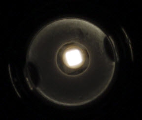
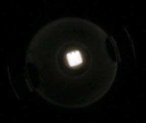
You can immediately see that most of the light comes direct from the LED, not from the surrounding reflector. Using an iris to block all except the direct light, and using the camera as a light meter, what I find is that roughly 80% of the light comes direct from the LED, again, only about 3 mm square.
Anyway, getting back to that snippet from Asha's post, michael_r's setup would surely have met the criteria that the illumination angle was small compared to even the narrowest entrance cone that he tested. In this case his system was acting coherent under all conditions he tested, so he always saw speckle.
I would guess, not knowing any more details, that in your setup the illumination came from a much larger effective source, in fact large enough that for small apertures your system behaved incoherent and thus had no speckle while for large apertures it behaved at least "partially coherent" and then did have speckle.
--Rik
-
ray_parkhurst
- Posts: 3439
- Joined: Sat Nov 20, 2010 10:40 am
- Location: Santa Clara, CA, USA
- Contact:
Yes, good guess. I diffused the lights with a 19mm diameter diffuser, and they were around 100mm away from the coin.rjlittlefield wrote: I would guess, not knowing any more details, that in your setup the illumination came from a much larger effective source, in fact large enough that for small apertures your system behaved incoherent and thus had no speckle while for large apertures it behaved at least "partially coherent" and then did have speckle.
--Rik
Based on this, I would expect a single LED, either undiffused or moved farther from the coin, to give a more speckle-rich result to a smaller aperture. I will give this a try.
I'm trying to figure out how to eliminate the speckles without compromising too much on other important aspects of coin photography, such as luster presentation (better with undiffused sources) and overall color balance. The speckles really mess up the apparent color of the coin.
-
rjlittlefield
- Site Admin
- Posts: 23626
- Joined: Tue Aug 01, 2006 8:34 am
- Location: Richland, Washington State, USA
- Contact:
I can see where that would be a balancing act.ray_parkhurst wrote:I'm trying to figure out how to eliminate the speckles without compromising too much on other important aspects of coin photography, such as luster presentation (better with undiffused sources) and overall color balance. The speckles really mess up the apparent color of the coin.
For some reason I'm reminded of the day that I first went shopping for a stereo dissecting scope, now some 43 years ago.
As I placed a coin under one of the scopes, the salesman made some comment like "not the best subject for this scope". I didn't press him for an explanation, though in retrospect I wish I had. The scope looked fine, I bought it, I still use it pretty much every day.
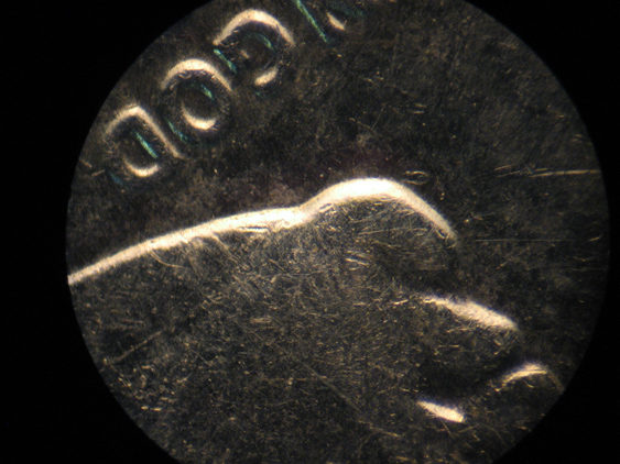
But now I think I understand what he meant about the scope and the subject. It turns out that the scope has no diffusion at all in the illumination path. It's a clear incandescent bulb, followed by some lenses and mirrors. The shape of the filament means that it's an extended source, but only in one direction. In the other direction it's quite narrow, and therein lies some great opportunity for speckle.
Here's an example. First the whole frame, a small part of a dime shot through the eyepiece at 45X. Then a pair, zoomed in to 70% of actual pixels, differing only in illumination.
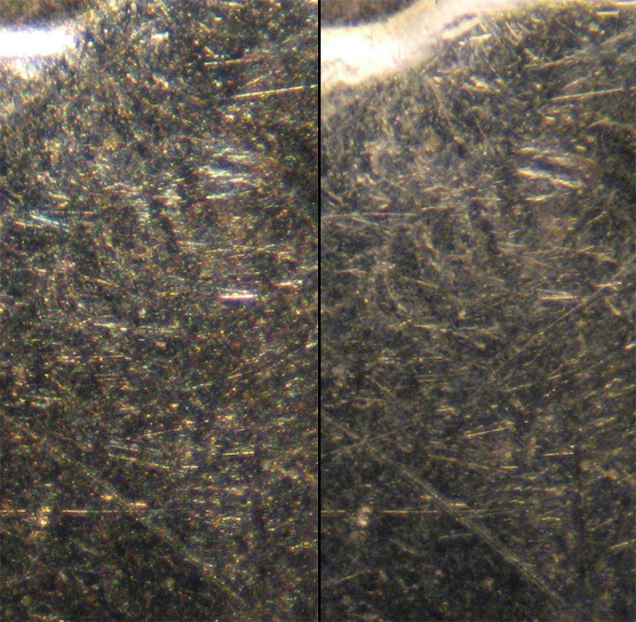
And what, you ask, is this magic diffuser that does such a great of getting rid of speckle and revealing finer detail? Well, it is truly an appropriate name: Scotch Magic Mending Tape, or at least the generic equivalent of that. A single layer of matte tape adds just enough diffusion to kill the speckle. Who would have guessed?
--Rik
-
ray_parkhurst
- Posts: 3439
- Joined: Sat Nov 20, 2010 10:40 am
- Location: Santa Clara, CA, USA
- Contact:
I have even used Scotch tape over my Jansjos! They run cool enough that you can do a lot of things you couldn't do with a hotter bulb.rjlittlefield wrote: And what, you ask, is this magic diffuser that does such a great of getting rid of speckle and revealing finer detail? Well, it is truly an appropriate name: Scotch Magic Mending Tape, or at least the generic equivalent of that. A single layer of matte tape adds just enough diffusion to kill the speckle. Who would have guessed?
--Rik
Most recently I discovered that the lens in the Jansjo is removable. It is held in place with a plastic ring that snaps over the white diffuser well. Remove the ring (carefully...I haven't broken one yet but it takes quite a lot of force to remove) and use the lens as a template for diffuser material (my favorite is Canson Opalux), then snap it back together with just the diffuser. The result is turning the very small apparent source of the Jansjo's phosphor-covered LED into a uniformly-lit 19mm dia source. Still not "big" but much easier to work with vs the tiny LED.
-
discomorphella
- Posts: 607
- Joined: Sun Oct 01, 2006 7:26 pm
- Location: NW USA
I've so far managed to keep out of this thread...but yes, this is a classic example of partial coherence (a regime where I live most of the time, since in optical lithography partially coherent imaging is our only method of transferring the information we have to image from a reticle onto a wafer in modern ULSI manufacturing and R&D). There are several good references for partially coherent imaging, this SPIE publication is a good one we use for training new engineers in the field;
http://spie.org/Publications/Book/2303
The J. Goodman references are all good, and these two will be of interest to Rik and others who want to delve into the underlying math
http://www.amazon.com/Linear-Systems-Fo ... 0471292885
as will the classic reference on the subject by Beran and Parrent.
http://www.amazon.com/Partial-Coherence ... B0006BLTBC
The papers by Hopkins are also good references
The Concept of Partial Coherence in Optics
http://rspa.royalsocietypublishing.org/ ... /263.short
On the Diffraction Theory of Optical Images
http://rspa.royalsocietypublishing.org/ ... /408.short
Applications of Coherence Theory in Microscopy and Interferometry
http://www.opticsinfobase.org/josa/abst ... a-47-6-508
The articles are behind pay walls but a library can get a copy and I'll try to figure out how to get an educational purpose copy for use for PMG. In fact, maybe we should have some forum topic like area for classic references and presentations etc?.
There are some more easily digestible review articles as well. I will see if I can figure out how to post them to PMG in a legally acceptable manner. Meanwhile, great thread.
David
Edit:
This Review of Modern Physics article by Mandel and Wolf is also a great, classic reference for Young's experiment and spatial coherence.
Coherence Properties of Optical Fields
http://journals.aps.org/rmp/pdf/10.1103 ... hys.37.231
Wow, I think that was one of my first posts on this forum...I'm glad to see the issue was resolved. Thank you discomorphella for weighing in with your experience!
I can't remember if I mentioned this before, but partial coherence aside, most camera sensors also have color noise. The artifacts can be corrected in post processing noise reduction.
I can't remember if I mentioned this before, but partial coherence aside, most camera sensors also have color noise. The artifacts can be corrected in post processing noise reduction.
-
Macro Photog
- Posts: 92
- Joined: Sat Dec 13, 2014 11:45 am
I know this is an old thread but it was very interesting to me and shed light on an effect I've experienced many times shooting minerals. Thanks to everyone who contributed to the thread - and my knowledge. I know the title says "from shiny metal", but I wanted to add it seems to occur for minerals as well.
Nick
Nick