Color from thin-film interference is very well understood with coin hobby. For example, read, this information on toned Morgan dollars. I'm quite confident it's not what's going on here.
Coins are not struck at an elevated temperature. They surely get a little warmer during striking, but they don't get "hot", certainly not hot enough to cause the sort of oxidation you're talking about. The rainbow-sparkle effect can be demonstrated on circulated coins, so any oxidation from the manufacture would have worn off (and new oxides formed through environmental exposure, greasy hands, etc.) and the surface is covered in micro-scratches. Proof coins with a mirror finish don't significantly show the effect, so it's not caused by some sort of heating/cooling deformation. Very fine surface texture IS departed to coins during manufacture, both from the metal grains but also from wear on the die.
False color and detail/DOF from shiny metal
Moderators: rjlittlefield, ChrisR, Chris S., Pau

This DoF explanation makes a lot of sense to me, but for what it's worth, I distinctly remember experiencing a lot more 'sparklies' on the old reversed lenses that I used to use 1 year ago than I do on the better modern stuff and diffusion I use now. Maybe that's just my changing technique.Joseph S. Wisniewski wrote: Collimated light is a "code", albeit a simple one. If you want to get rid of the interference, you need to strip the light of all coding, which means, as Rik saw, you make sure rays are coming in on every possible trajectory.
That is also how the speckles increase DOF. They do that because there's such small numbers of them. If there were more ray trajectories, you'd get more speckles, and they'd average each other out into a blur.
My extreme-macro.co.uk site, a learning site. Your comments and input there would be gratefully appreciated.
I don't want to get into arguments about people's prized possessions!. In the UK we sometimes get colours like those on new and circulation coins, and as far as I know it's not a big deal.
I thought you meant smaller scale sparkle than those are showing, which would be more applicable to macro photos, so was thinking of grain-sized causes.
I didn't see anything which helps us, as such, in that article? They all look like oxidation to me. Note that oxidation of a metal is loss of an electron, so sulphur will do, oxygen doesn't have to be involved in the slightest for oxidation to occur! Different oxidising agents may be responsible for the different runs of colours you get as they progress. If you're a metal, half the periodic table is out to get you, (including some other metals) - and they could be compounds. I have no idea what, eg, silver sulphate (Ag2SO4) films looks like.
You don't need heat for oxidation - as I said, it starts as soon as a fresh (non-noble) metal surface is exposed to air, and grows immediately. Remember you may not see it until it gets thick. The wavelength of light is thousands of layers. It may take hundreds plus, of atoms thickness to change the colour.
The speed of formation of the oxide, and presence of other agents, would alter its appearance too.
Even way back when I was doing metallurgy, it would have been very simple to put a coin in a SEM with an analyser to see what was in the surface layers. (Eg an electron beam makes X-rays come off, at characteristic wavelengths).
At one point I was sectioning oxidised metal to look at the different oxides which form through the thickness of an oxide layer formed in a reactor. The composition in that case changed radically through the thickness. Tiny changes in the composition of the metal alter the oxide film a lot - and nothing's 100% pure, not even new coins! Were they "pure" silver dollars? If so, they would have had a little copper in there, and so on. I was using lab-grade materials, and still found unexpected elements.
None of the coins on that page seem to show the sort of colour which is a problem in macro photography?
A large interesting effect is visible in what it refers to as "pullaway" though, where the structure of the metal might have been locally different due to the stamping. That would have an effect, as I said earlier, on oxide growth - some oxides more than the quickly/artificially created ones, perhaps..
I think we're getting off topic!
-
rjlittlefield

- Site Admin
- Posts: 23603
- Joined: Tue Aug 01, 2006 8:34 am
- Location: Richland, Washington State, USA
- Contact:
Sorry, I should have been more explicit.ChrisR wrote:I can see differences in resolution in the wedding band, the colours seem to be there in both, more strongly noticeable where the highlights are brighter? Is this full frame?
What I posted earlier are 100% pixel crops from a Canon Powershot SD700 IS camera pointing through the eyepiece of a microscope, handheld and operated with focus/exposure lock by maintaining half-press of the expose button. The objective is a CF N Plan Achromat 10X NA 0.30; eyepieces are 10X. The photos are separated by a few seconds and differ in that for diffusion a single ply of double-ply facial tissue was held between the JANSJÖ lamp and the ring. (No, I'm not trying to be funny with this level of detail. Any or all if it could conceivably matter.)
Full frame, the images look like this:
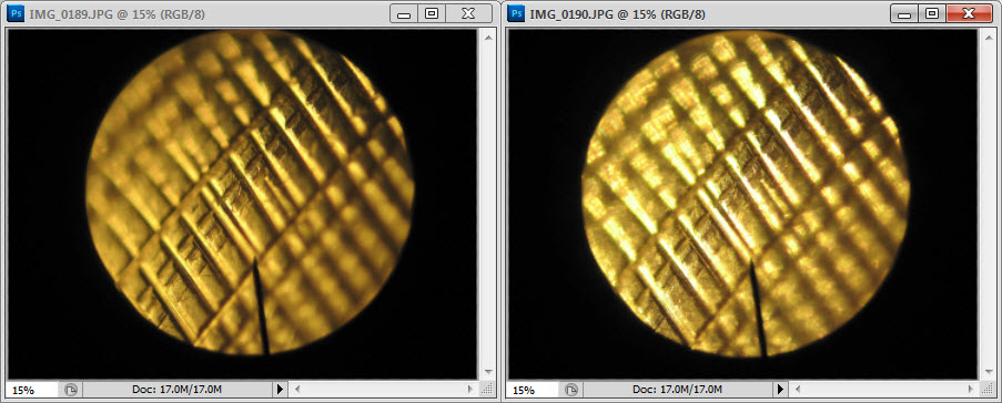
Here again are the crops:
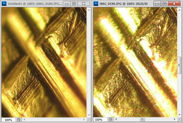
The mischief and interesting effects that I intended to highlight were the speckle and colors mostly in the well exposed and focused areas along the diagonal from lower left to upper right in the crops. I think that some of the broad color shifts near the blown highlights are due to sensor overload. I think I'm also seeing longitudinal CA, with green fringes on one side of focus and red on the other.
The pointer in the full frame means nothing; I just happened to shoot through the eyepiece that has one.
--Rik
-
CaptainFwiffo
- Posts: 54
- Joined: Sun Jul 29, 2012 10:45 am
ChrisR, we're definitely talking past each other. The link to the Morgans was to show an example of coloring on coins caused by oxidation (and some discussion of the cause of the colors - something that is well known in the coin hobby).
What I'm saying is that the rainbow-sparkle effect I'm seeing on macro images of coins under LED lighting is completely different from that, and is not oxidation, and is, in fact, the same phenomenon being shown in the original post of the thread. It's somehow caused by the micro-texture of the coin's surface interacting with a harsh, near point-like light source like LED lighting.
What I'm saying is that the rainbow-sparkle effect I'm seeing on macro images of coins under LED lighting is completely different from that, and is not oxidation, and is, in fact, the same phenomenon being shown in the original post of the thread. It's somehow caused by the micro-texture of the coin's surface interacting with a harsh, near point-like light source like LED lighting.
Righto, I'm with you now. All I could see before (laptop screen) was a slight blue tint to the image you posted before.
I've pushed the saturation up:

Well, that's different!
Dunno.
Must say that while I was pushing the slider up and down it didn't quite look like the brushed steel's, or gold's surface. There isn't the association with the scratches...?
If it's colours from surface patches of something, the colours might change as you rotate the coin but the patches would have the same boundaries. Some of them now look like paint splashes, big enough in relation to the shapes on the coin that they should be easy to locate, if they stay where they are.
Some of the colours look like they're reflecting in the sides of the letters?
Some of the detail is lost in the jpeggy squares, in the posted image. Can you go closer with your optics?
.
Are these silver, too?
I have some 95% silver coin somewhere (pre 1917 shillings). I could wash then in hydrochloric acid then whack them with a shiny hammer...
I've pushed the saturation up:
Well, that's different!
Dunno.
Must say that while I was pushing the slider up and down it didn't quite look like the brushed steel's, or gold's surface. There isn't the association with the scratches...?
If it's colours from surface patches of something, the colours might change as you rotate the coin but the patches would have the same boundaries. Some of them now look like paint splashes, big enough in relation to the shapes on the coin that they should be easy to locate, if they stay where they are.
Some of the colours look like they're reflecting in the sides of the letters?
Some of the detail is lost in the jpeggy squares, in the posted image. Can you go closer with your optics?
.
Are these silver, too?
I have some 95% silver coin somewhere (pre 1917 shillings). I could wash then in hydrochloric acid then whack them with a shiny hammer...
-
CaptainFwiffo
- Posts: 54
- Joined: Sun Jul 29, 2012 10:45 am
Tonight I got to wondering what the colored sparkles of a coin might look like under greater magnification and resolution. So I looked at a U.S. nickel, first at low mag, then moving up. At low magnification, the sparkling colors looked much like those of the other coins in this thread. As I increased the magnification, the character of the colors didn't seem to change—but it became increasingly easy to parse individual colors and dark lines between the colors. By 50x and 100x, the entire ROYGBIV spectrum was easy to see; lines reminiscent of airy disks and their linear equivalents were apparent. To my eye, this looks like diffraction/interference (really two descriptors of a single phenomenon). Would it be fair to surmise that the surface of the coin is acting as a reflective diffraction grating?
Please click here to see an animation of 10 shots taken by racking focus in and out at 0.5 micron intervals with a Mitutoyo 100x 0.70 objective.
One shot from the animation. (Don’t worry that it’s not "sharp,"—for exercises like this, we want to push into boundary conditions looking for maximum information, at the sacrifice of crisp appearance. This image was shot at F/71—deeply into diffraction territory--then cropped to actual pixels, then upsized by a factor of 4 for viewing convenience.)

Technical info: Nikon D200 APS-C camera, Mitutoyo Plan Apo 100x/0.70 lens. Continuous halogen light, through undiffused fiber optic light guide. Tip of light guide (10mm diameter lighting area) was about 28cm from subject, to subject right, at about 30 degrees to camera side of subject plane. All images were jpegs straight out of camera--no color or contrast enhancement, no sharpening.
--Chris S.
Please click here to see an animation of 10 shots taken by racking focus in and out at 0.5 micron intervals with a Mitutoyo 100x 0.70 objective.
One shot from the animation. (Don’t worry that it’s not "sharp,"—for exercises like this, we want to push into boundary conditions looking for maximum information, at the sacrifice of crisp appearance. This image was shot at F/71—deeply into diffraction territory--then cropped to actual pixels, then upsized by a factor of 4 for viewing convenience.)
Technical info: Nikon D200 APS-C camera, Mitutoyo Plan Apo 100x/0.70 lens. Continuous halogen light, through undiffused fiber optic light guide. Tip of light guide (10mm diameter lighting area) was about 28cm from subject, to subject right, at about 30 degrees to camera side of subject plane. All images were jpegs straight out of camera--no color or contrast enhancement, no sharpening.
--Chris S.
Neat.
Most of the rings/fringes would be varieties of Fraunhofer patterns, eg for a circular aperture: http://en.wikipedia.org/wiki/Fraunhofer ... r_aperture .
Angles depend on size of the source, aperture of the lens. (See Airy disc).
It's similar for gratings (repeated micro-ridges on a surface?), which predict the spacing of the fringes.
Many of the patterns we see coming off a random scratch's edge resemble the patterns predicted for a "rectangular aperture"?
Whatever's happening, it seems clear that this movement is not the same as the shifting-about of the features in Rik's bug, observed as he focused.
I would like to call in to a met lab, polish a piece of metal, and scratch across it with an ultra-microtome knife, and look at that. Anything that's been bashed out in a factory or handled, is just so covered in irregularities. A lab-prepared, polished metal specimen shows no surface detail with an optical microscope at 400x. Normal polishing slurries go to 0.02micron.
I've just read of knives going down to 20nm. I have a lump of obsidian and a hammer..
Hmm, looking at the edge of a new razor blade might be interesting.
Going back to Chris_S's carbon, if it's "just soot" then it would be some amorphous carbon mix, ( http://prb.aps.org/abstract/PRB/v35/i6/p2946_1 ) randomly arranged tiny graphitic plates/rings of atoms. Point light-sources much less than the wavelength of light in diameter? Beyond my understanding, but might explain why the rings we can see look similar sizes, if something else (combined NA?) is determining it than particle size.
I feel we have a way to go yet to explain all the oddities: the pin pricks of colour, and some of the directional, coloured or white flary things we see which depend where the illumination is coming from. And the coin sparkles visible with no lens, perhaps.
Off to make some soot, a telecentric lens, cover over half a high NA lens, try to make some metal sparkle, etc...
Thinking more about this, I believe it’s useful—even if not intended—that we’re discussing more than just the “colored sparklies” in this thread. Although it may seem unrelated, the increased depth of field and decreased resolution observed with some subjects illuminated with small light sources probably does deserve its inclusion, here. Ditto the startling observation that with small light sources or small, non-centered test apertures, out-of-focus elements move across the visual field as focus is adjusted. Whatever we’re seeing, these elements surely all come to bear.
It may be important, when interpreting images of the sparklies, to bear in mind that when shooting something like a coin or soot with a small light source, we are not filling the entire aperture of the lens with light. We are using only part of the lens’ aperture—a function of the pointiness of the light source and the limited light-scatter of the subject, gated by the numerical aperture of the lens. Since we are utilizing only part of the numerical aperture, let me call this the “utilized aperture”—until somebody tells me what the official term is, if such exists. The utilized aperture may be the full numerical aperture, as in the case of diffused light sources or subjects that scatter light evenly; or it can be less than the numerical aperture, as in the case here. Limiting the utilized aperture to less than NA can also be done by blocking part of the lens, as Rik did in his experiments with pins.
We’re used to thinking of resolution and depth of field as being determined by the effective aperture—and for many subjects in typical lighting, it is—but in cases where less than the full effective aperture is in the light path, it is that portion actually used (I’d call it the “utilized effective aperture”) that determines resolution and DOF. An important corollary is that the subject itself—its overall texture and micro features—have a big impact on utilized effective aperture. It’s not just the lens that determines aperture—in the scenarios discussed in this thread, it is the combination of subject and lighting, as gated by the lens, that determines utilized aperture. Once we get used to the subject being involved, it becomes more intuitive that the utilized aperture need not be round, and need not be uniform—it may vary across the subject, from image detail to image detail.
It may be a good idea to consider this when the word "aperture" comes up. I found the concept intriguing when considering some of ChrisR’s observations:
-------------
But does the shifting of out of focus surface features have much to do with shifting of colors? I don’t know. If I were to show two animations of the whole frame, you would see apparent color movement mostly along the picture’s vertical axis in the one lit from above, and the horizontal axis in the one lit from the right. (I didn’t shoot a series with the light above the subject—merely observed the effect of turning the focus knob, and shot a few stills along the way). The small crop does have the appearance of being influenced more by local surface features than the direction of light—so you well might be right in your observation. I just think we should be careful about it until further testing.
This is fun stuff, and we might even be getting somewhere!
--Chris
--edited for typo
It may be important, when interpreting images of the sparklies, to bear in mind that when shooting something like a coin or soot with a small light source, we are not filling the entire aperture of the lens with light. We are using only part of the lens’ aperture—a function of the pointiness of the light source and the limited light-scatter of the subject, gated by the numerical aperture of the lens. Since we are utilizing only part of the numerical aperture, let me call this the “utilized aperture”—until somebody tells me what the official term is, if such exists. The utilized aperture may be the full numerical aperture, as in the case of diffused light sources or subjects that scatter light evenly; or it can be less than the numerical aperture, as in the case here. Limiting the utilized aperture to less than NA can also be done by blocking part of the lens, as Rik did in his experiments with pins.
We’re used to thinking of resolution and depth of field as being determined by the effective aperture—and for many subjects in typical lighting, it is—but in cases where less than the full effective aperture is in the light path, it is that portion actually used (I’d call it the “utilized effective aperture”) that determines resolution and DOF. An important corollary is that the subject itself—its overall texture and micro features—have a big impact on utilized effective aperture. It’s not just the lens that determines aperture—in the scenarios discussed in this thread, it is the combination of subject and lighting, as gated by the lens, that determines utilized aperture. Once we get used to the subject being involved, it becomes more intuitive that the utilized aperture need not be round, and need not be uniform—it may vary across the subject, from image detail to image detail.
It may be a good idea to consider this when the word "aperture" comes up. I found the concept intriguing when considering some of ChrisR’s observations:
Most of the rings/fringes would be varieties of Fraunhofer patterns, eg for a circular aperture: http://en.wikipedia.org/wiki/Fraunhofer ... r_aperture .
Angles depend on size of the source, aperture of the lens. (See Airy disc).
Many of the patterns we see coming off a random scratch's edge resemble the patterns predicted for a "rectangular aperture"?
-------------
From the small images I provided, it does look like these are different phenomena. But having seen a lot more during the exercise, I think we should reserve judgment on this point. I also tried shooting the coin with the light shifted 90 degrees from its position in the images shown (that is, instead of being to subject right, it was above the subject—but at the same approximate distance and angle to the subject plane). Boy, did I see shifting! This was not necessarily shifting of the colors, but of the out-of-focus surface features. My first thought was that I didn’t have the coin aligned as carefully as I’d thought (perpendicular to the lens axis, and adjusted with reasonable care using my goniometers and rotation stage). But this was an old thought-habit—within a few seconds, I realized I was observing Rik’s moving pins effect. This, by the way, solved a long-standing riddle for me: I’d often noticed what I thought was a small misalignment in my rig, which resisted all my efforts to characterize or eliminate it. With a slap to the head, I recognized that what I’d been seeing was Rik’s moving pins effect, not misalignment.Whatever's happening, it seems clear that this movement is not the same as the shifting-about of the features in Rik's bug, observed as he focused.
But does the shifting of out of focus surface features have much to do with shifting of colors? I don’t know. If I were to show two animations of the whole frame, you would see apparent color movement mostly along the picture’s vertical axis in the one lit from above, and the horizontal axis in the one lit from the right. (I didn’t shoot a series with the light above the subject—merely observed the effect of turning the focus knob, and shot a few stills along the way). The small crop does have the appearance of being influenced more by local surface features than the direction of light—so you well might be right in your observation. I just think we should be careful about it until further testing.
It’s definitely soot. If you’re trying to replicate the structure (probably not at all important), it may be important to know that this was airborne particulate collected with a sampling machine—essentially a box with a fan pulling air in and blowing it through a flat filter made of glass fibers. Soot deposited directly on, say, a microscope slide held in a candle flame, might or might not behave similarly.Going back to Chris_S's carbon, if it's "just soot" then it would be some amorphous carbon mix. . . .
This is fun stuff, and we might even be getting somewhere!
--Chris
--edited for typo
Last edited by Chris S. on Tue Jun 25, 2013 3:06 pm, edited 1 time in total.
-
rjlittlefield
- Site Admin
- Posts: 23603
- Joined: Tue Aug 01, 2006 8:34 am
- Location: Richland, Washington State, USA
- Contact:
Chris S, thanks for the great illustrations and careful analysis.

But I have the feeling that we must be reinventing quite a lot of this material. There's nothing wrong with that and often it produces new insights. Still, I would like to know what other people have already figured out. Can anybody find a reference, say, to some articles or textbooks where metalurgists learn how to "read the speckles", as Joseph puts it?
--Rik
That seems like a great summary.Chris S. wrote:Once we get used to the subject being involved, it becomes more intuitive that the utilized aperture need not be round, and need not be uniform—it may vary across the subject, from image detail to image detail.
Let's see... The out-of-focus movement effect depends on the light path from subject to lens. If local surface features act like random mirrors, then the angles of the paths will vary randomly also, with the light direction being strongly correlated with the individual features. At the same time, it seems like there's going to be some correlation between the distribution of angles of the mirrors and the averaged slope of the surface, so if we back off and look at some ensemble average we should see a slope-of-the-surface effect. I don't immediately see anything inconsistent about this.The small crop does have the appearance of being influenced more by local surface features than the direction of light—so you well might be right in your observation. I just think we should be careful about it until further testing.
Indeed!This is fun stuff, and we might even be getting somewhere!
But I have the feeling that we must be reinventing quite a lot of this material. There's nothing wrong with that and often it produces new insights. Still, I would like to know what other people have already figured out. Can anybody find a reference, say, to some articles or textbooks where metalurgists learn how to "read the speckles", as Joseph puts it?
--Rik
Couldn’t agree more, but we’ve been accepting that “it’s just the way light works”, for a while now; nobody seems to have come across too many explanations yet!I have the feeling that we must be reinventing quite a lot of this material.
I think the tied notions of the restricted aperture, associated with a surface feature, most obviously when it’s a bright spot, causing the extended dof and moving in undesirable ways, is the most useful thing to have come out of the thread. Page 2.
I don’t remember seeing that before.
The unexplained colours, don’t seem to me to be moving in ways consistent with the ray path alone, but I can’t make a good demonstration of why. Perhaps there’s mileage in using a telecentric setup (Nikon CFMplan 20x ELWD is close).
There’s lots of gaps in my understanding - I never studied anything like this. Y’all guessed, huh? I’m musing away assuming nobody much is reading…
Normal subjects show detals on the sensor, from light reflected off the subject approximately isotropically. It seems that when they get more directional, then we see movements. When we see a really strong highlight producing a flary thing from a directional illumination, the movement is pronounced, and extends into focus stack steps where everything else local, is out of focus. (I’ll try to repeat the problem with the 100x objective, it’s all not usable at the moment). Ray paths work for those.
But I’m thinking the coloured blobs, assuming they’re from interference (diffraction), are different, because they are not ON the subject, they’re a result of constructive interference creating them at the sensor (or in your eye).
The difference in path-lengths from the feature on the subject happens to cause the interference showing on the sensor. Think of two wave-fronts arriving at the sensor, from slightly different angles. If two wave-crests come together right, you get a bright blob. The wavefronts cross, like an X. The next wave-front is only half a micron (approx) behind, so if you focus very little, it depends on the angles of the X, but the intersection you had, could be way off to one side. I’m strugging to draw how it works correctly, in my head or on paper, but I can’t see it just simply fitting the normal ray-paths. Look at Chris_S’s animation: There’s a point just under half way up, above the “0” in “10”, around which there are concentric circles. They don’t move around much during the focusing. Further up, there’s parallel fringes breathing apart and together by +40% or so. Just ray paths, really? How come? I've got part way with constructing something, but I pass.
For interference to occur, you have to have a coherent light source. That’s the single slit in the Young’s Slits experiment. Towards a point source of light, a stable phase relationship in your standing waves.. In other words, hard light. (Try pin-pricked foil tape stuck over your cell phone’s led – it works quite well). If the light source is too big, the subject sees waves coming from too many directions.
The next thing you need is a pretty small reflecting subject/pin hole/narrow pair of slits, to do the diffracting. If you have an area (pin hole or flake of metal) doing it rather than separate slits, it works like waves are coming off each edge of the area, and interfering. (That’s why a rectangular feature gives a crosslike Fraunhofer pattern.)
So there’s a kinda “coherent zone” that the
>light source size / distance,
and
>subject feature size,
have to be in. The maths isn’t too desperate but I’ll refrain from making predictions. The angles for bright constructive fringes are small.
If you move your cellphone light source around, the coloured blobs do move about. They usually go faster than the principal light. The reflections from the relevant reflecting/diffracting sources on the surface head off into different parts of the objective along the ray paths, with their wave functions, each something like Rik’s Airy disc picture, or wider Fraunhofer pattern, or better-blobbed and more separated pattern like that from an opal, if the surface were better structured. Then they’d interfere with each other, in ways I suspect are rather mangled compared with the textbook drawings from nice simple gratings and apertures. Back to those X shapes.
On top of the pretty, fairly ordered patterns, there's Speckle - patterns from a mutually interfering set of wavefronts (looks like semi-random noise), and Fresnel diffraction, which is what happens [edit] near to the object when the rays hit it. Possibly appearing in Chris_S's soot, as Rik suggested.
Edit - Fresnel diffraction is near field, and may be doing more than I can find a desription for. Fraunhofer patterns are far field.
Last edited by ChrisR on Fri Mar 01, 2013 5:33 am, edited 1 time in total.
Opals, surface features as diffraction grating:
http://www.webexhibits.org/causesofcolor/15F.html
Note the separation between the principal ray and the blobs of colour. You can tip an opal about and the colours don't move very much, unlike an Airy disk.
http://www.webexhibits.org/causesofcolor/15F.html
Note the separation between the principal ray and the blobs of colour. You can tip an opal about and the colours don't move very much, unlike an Airy disk.
Phew - finally found an article which heads in a good direction:
http://mysite.du.edu/~etuttle/optics/ywave.htm
He starts with an unusual approach to the maths, but stick with it, it still isn't too scary when he mentions - tadaa
lustre on metals in sunlight
He's putting numbers to the "coherence zone" I referred to a couple of posts ago. He uses "h" for both the distance between slits (~= particle size) then later in the same paragraph for the distance from the illumination to the subject, but hey ho.
Yay!
----------
There's an associated but different issue - Speckle.
Be careful!
Definitions of what it means get blurry. It's to do with interference between all the light that's in there when there's enough of it that's coherent, and leads to noise-like dots of colour. The colour coming off the Opal, is not, I think, what would be generally called speckle; it's too ordered.
Similarly, the coloured rings from Rik's Airy disc aren't called speckle.
There's an appealing-looking article to which Chris_S sent me a link, which talks about Speckle. It refers to speckle as the definition of coherence ( backwards logic? ). To me it appears to confuse the issue of what happens in , eg Chris_S's picture above.
It's very relevant: you only start to get it when the light is coherent enough, (as worked through in the mysite.du.edu article, which didn't need the word "speckle" to get there) .
It may be all the reader needs if the question is only "Why do we get coloured dots".
The paragraph
"In U.S. engineering practice, surface roughness was expressed in microinches. One ten-thousandth of an inch, 0.0001" is 100 μin. This is the roughness of a normal well-machined surface. Since a typical visible wavelength is about 13 μin, this corresponds to about 8 wavelengths. Such a distance is even larger than the coherence length of a monochromatic beam from a discharge lamp, so speckle is not observed with such a coherent source. When the roughness of a surface is about 10 μin, on the other hand, there is specular reflection and again speckle is not observed."
is presumably what was meant by "reading the speckle"- it only works for a range of surface feature size.
Most articles on speckle refer to laser light, because it's coherent. As I understand it we only see colours from, eg sunlight, because there are bursts of coherent light when things happen to work out.
I just came across an article which may make someone say "what's all that technical guff about, it's under your nose:"
http://web.archive.org/web/200906120700 ... e0705.asp/
(note the very last line, about Pluto.)
-
rjlittlefield
- Site Admin
- Posts: 23603
- Joined: Tue Aug 01, 2006 8:34 am
- Location: Richland, Washington State, USA
- Contact:
ChrisR, thanks for the continuing investigation. I am reading; I'm just short of time right now to think very hard about this problem.
A couple of quick comments that may help...
Covering over part of a high NA lens could be very informative. Consider the simple experiment of placing in front of the objective a small black card with a hole in it that limits the full potential aperture to some much smaller available aperture. Then move the card around laterally, so that the available aperture also moves around. If you do this with a 3D subject and diffuse illumination, you'll see OOF details move around as predicted by the ray path argument. But what happens to the colored patterns? Do they just move around, or do they wink into and out of existence, or dramatically change their nature? The issue -- which I am not clear about! -- is how and how much the patterns that end up on the sensor depend on the lens aperture versus just the surface and the illumination.
Regarding speckle, see also http://en.wikipedia.org/wiki/Speckle_pattern. They describe it as the interference pattern produced by a surface with random texture. The point you mention about coherence length is critical. Lasers are coherent over huge distances, so the speckle pattern can be large also. For ordinary "incoherent" light, the limited amount of coherence is only over much shorter distances, leading to that critical size range you mention.
I suspect that in Chris_S's images, we really are seeing speckle over much of the area, in the sense that it's the interference pattern resulting from a bunch of uncorrelated or weakly correlated surface perturbations, as opposed to the strongly correlated perturbations of points on a scratch or dimple.
--Rik
A couple of quick comments that may help...
I don't think the telecentric lens will give you any new information. As mentioned earlier, these colored pattern effects all occur in the center of the field (as well as elsewhere), and in the center of the field telecentric lenses have no special properties because all lenses have their entrance cones parallel with the optical axis.Off to make some soot, a telecentric lens, cover over half a high NA lens, try to make some metal sparkle, etc...
Covering over part of a high NA lens could be very informative. Consider the simple experiment of placing in front of the objective a small black card with a hole in it that limits the full potential aperture to some much smaller available aperture. Then move the card around laterally, so that the available aperture also moves around. If you do this with a 3D subject and diffuse illumination, you'll see OOF details move around as predicted by the ray path argument. But what happens to the colored patterns? Do they just move around, or do they wink into and out of existence, or dramatically change their nature? The issue -- which I am not clear about! -- is how and how much the patterns that end up on the sensor depend on the lens aperture versus just the surface and the illumination.
There's no trouble seeing spectral colors if you catch glancing light coming off a CD. That's because the CD has highly regular grooves extending over large areas of its surface, causing the diffraction spectra to be large and very well defined. My guess is that colored sparkles are just a small-scale version of this same phemonenon -- regular striations over a region that is just barely large enough to be detected by eye.And the coin sparkles visible with no lens, perhaps.
Opals are odd. With them the colors are not so much a surface effect as a volumetric effect. Some of the effect there strikes me as more like a photonic crystal. (I see that http://en.wikipedia.org/wiki/Photonic_crystal actually uses an opal for illustration.)Opals, surface features as diffraction grating
Regarding speckle, see also http://en.wikipedia.org/wiki/Speckle_pattern. They describe it as the interference pattern produced by a surface with random texture. The point you mention about coherence length is critical. Lasers are coherent over huge distances, so the speckle pattern can be large also. For ordinary "incoherent" light, the limited amount of coherence is only over much shorter distances, leading to that critical size range you mention.
I suspect that in Chris_S's images, we really are seeing speckle over much of the area, in the sense that it's the interference pattern resulting from a bunch of uncorrelated or weakly correlated surface perturbations, as opposed to the strongly correlated perturbations of points on a scratch or dimple.
--Rik