rjlittlefield wrote:elf, I'm a little confused here. Bear with me, please.
First off, let me make sure I understand the situation you're trying to handle.
I think you're working with a bellows setup that focuses by moving the camera, that is, changing the camera-to-lens distance. With that kind of setup, magnification onto the sensor changes along with focus. As you draw the camera back, the magnification gets greater, hence the DOF gets smaller. Thus in order to get a constant percentage overlap, you need to move the focus plane a smaller amount also. The challenge is to determine exactly how much to change the bellows draw -- the camera-to-lens distance -- in order to maintain constant percentage overlap of the in-focus slabs.
Have I got that right so far?
Assuming so, then I gather that the purpose of the spreadsheet is to calculate bellows draws that maintain that constant percentage overlap.
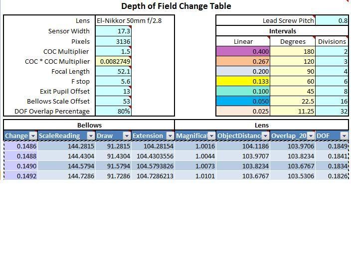
Further complicating the issue is that it's physically difficult and error-prone to set the bellows draw to arbitrary values. Hence, I gather you've decided that a good approximation is to change the bellows draw by easily set amounts that correspond to nice fractions of a full turn on some dial. Those amounts (in the current spreadsheet) range from 0.025 mm at 1/32 turn, up to 0.400 mm at 1/2 turn. Each of the easily set amounts is assigned a color code, and the table of computed draws is correspondingly color-coded in big blocks.
Now I'm trying to imagine the workflow.
I choose my parameters and plug them into the table at the top of the spreadsheet. For the sake of experiment, I choose f/4. Then I push the "Recalculate the Table" button and wait until the table is recalculated. This requires 9-1/2 minutes on my 1-year-old quad-core 2.4 GHz processor using Excel 2007. When the table is completed, it contains a list of ScaleReadings.
Then I guess I set the bellows to the first ScaleReading and take my first picture. To advance from picture to picture, I look at where the bellows is currently, find the closest ScaleReading, look at the color of the corresponding change, and advance the dial by the appropriate part of a turn. This process continues, using a constant step size, until the bellows has advanced into a different color block, at which point the step size changes. Then the process continues, using that new step size.
That's right. I'm not so much concerned about having equal steps or overlap as making sure each step is smaller than the DOF for that image. Live View is definitely not good enough to judge DOF accurately.
I'm mystified why it would take so long on your computer. It usually only takes a minute or two on mine. (Dual Core X86 with 4gb of memory)
My workflow is usually:
1. Select the magnification or closest focus point on the subject. This also sets the composition.
2. Verify there is enough camera movement to get the farthest desired point in focus.
3. Set the bellows draw to ScaleReading for the focus point selected in step 1.
4. Enter the table to find the focus step. Usually I just use the color code to decide how far to step.
5. Snap the shutter.
6. Move the camera the specified amount.
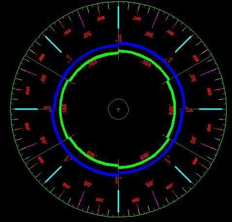
7. I have the points marked on the bellows scale where to switch to the next focus step size. The scales just slip in and out so it's real easy to create a custom scale for each lens and aperture setting. I also have the dial that drives the leadscrew marked with the same divisions as the color coded table.
8. Repeat steps 5 and 6 until the frame is done.
There are several advantages to moving just the camera instead of the camera and lens as a unit or moving the subject.
1. The movement is a lot larger for each step at higher magnifications. For example at 2X the step would be 0.222 or 90 degrees compared to .0692 or 22.5 degrees. At higher magnifications this would be a much larger difference.
2. Having the lens in a fixed spot allows panoramas to easily be stitched
The table will work for determining the focus step where the camera and lens move as a unit or the subject is moved. Just use the setting in the DOF column for the magnification desired instead of the Change column to set the focus step.
rjlittlefield wrote:
Am I still on track? I ask because if I'm not, then I'm seriously confused, and if I am, then I'm still pretty confused because the color codes seem wrong. At the top of the table, the steps are around 0.0615 and they're coded green, but the green intervals are 0.100. So if I make a "green" step (0.100 mm), then I've moved too far and lost my overlap. Likewise, much farther down, the steps get big enough to transition from green to yellow, but that happens at a point where the required step as computed is 0.100 but the new physical step will be 0.133.
Obviously I'm missing something here. Can you clear up my confusion?
--Rik
You're right, I used a less than instead of a greater than symbol in the color coding section. My excuse was it was late at night

I've updated the online copy.