Cylindrical polarizer - crossed polarizer

A forum to ask questions, post setups, and generally discuss anything having to do with photomacrography and photomicroscopy.

Moderators: rjlittlefield, ChrisR, Chris S., Pau

AndrewC
Posts: 1436
Joined: Thu Feb 14, 2008 10:05 am
Location: Belgium
Contact:

Cylindrical polarizer - crossed polarizer

Post by AndrewC »

Some examples from a line of thought I've been pursuing using cross polarization with a polarizing film formed into a tube around the subject.

First image is the setup - subject is enclosed inside a diffuser made up of a plastic tube lined with diffuser material lined with the "source" polarizing film. The film is aligned with the axis of polarization either orthogonal or coaxial to the tube.

There is an adjustable Cir-Pol "analyser" filter between the lens and sensor.

Lighting is from two snooted SB-23 strobes, one either side of the tube.

Images are in pairs with the "analyser" filter at max extinction and 90deg rotation to show the cross-polarizer affect.

When re-shooting these I found it easiest to get max extinction with the source polarizer aligned co-axially, on other subjects I've found it easier in the orthogonal alignment. I find this technique very subject dependent - depends on the alignment of the different reflective planes ?

Equipment setup:

Image

Orthogonal source filter:

Image

Coaxial source filter:

Image

Orthogonal with 10x objective:
Image
rgds, Andrew

"Is that an accurate dictionary ? Charlie Eppes

Pau
Site Admin
Posts: 6072
Joined: Wed Jan 20, 2010 8:57 am
Location: Valencia, Spain

Post by Pau »

Andrew, this is a very interesting experiment, but I can't see the typical effect of the cross pol illumination: supression of the specular reflections. Some one commented in the forum that a metallic beetle under cross pol looks black. Did you shot the some subjet but without the polarizing cilynder to compare the effect?
Pau

ChrisLilley
Posts: 674
Joined: Sat May 01, 2010 6:12 am
Location: Nice, France (I'm British)

Post by ChrisLilley »

Andrew, does the whole lens rotate when you rotate the polariser?

Pau
Site Admin
Posts: 6072
Joined: Wed Jan 20, 2010 8:57 am
Location: Valencia, Spain

Post by Pau »

I finally found the source: It was from Rik, of course! :lol:
When illuminated by non-polarized glancing light near Brewster's angle, the reflections become highly polarized as one would expect for an organic material. However, when illuminated from the front, the cuticle acts more like blue metal. If the front illumination is non-polarized , the shiny blue cuticle adds no obvious polarization of its own, and when illuminated by polarized light, it preserves that polarization. This means that using crossed polarizers to kill specular reflections is a complete disaster. When arranged to eliminate the unpleasant reflections of my tiny fiber optic bundle, crossed polarizers made the whole wasp go black!
but with a wasp
http://www.photomacrography.net/forum/v ... A&start=15
Pau

Bob^3
Posts: 287
Joined: Sun Jan 17, 2010 1:12 pm
Location: Orange County, California

Post by Bob^3 »

AndrewC wrote:Some examples from a line of thought I've been pursuing using cross polarization with a polarizing film formed into a tube around the subject.
Andrew,

I’m also deeply interested in this concept. I have just completed a setup to test a high-tech diffusion material detailed in this thread (I hope to post the results from this within a few days):

http://www.photomacrography.net/forum/v ... hlight=lsd

My intention is to test various configurations of wrap-around diffusers including tunnels like you show here with polarizing film on the source and lens, to determine if this is a feasible solution for reducing specular reflections.

After reading the recent thread started by Charles and the older threads by you and Rik on this topic, I realized that this concept is difficult to visualize---intuition failed to provide a clear answer. So last night I made some test images, which may add additional data and help shed some (polarized :D ) light on the subject. Do you mind if I post them here?

Bob
Bob in Orange County, CA

AndrewC
Posts: 1436
Joined: Thu Feb 14, 2008 10:05 am
Location: Belgium
Contact:

Post by AndrewC »

Bob^3 wrote:.. Do you mind if I post them here?..

Bob
Not in the slightest :) It's an interesting and, IMHO, highly empirical topic.

I'm planning to extend this test with other options - large arch with the film a long distance from the subject, squared "bridge" with vertical sides and top, and other things that take my fancy.

Andrew
Last edited by AndrewC on Fri Nov 12, 2010 12:07 pm, edited 1 time in total.

AndrewC
Posts: 1436
Joined: Thu Feb 14, 2008 10:05 am
Location: Belgium
Contact:

Post by AndrewC »

ChrisLilley wrote:Andrew, does the whole lens rotate when you rotate the polariser?
Yes the whole lens rotates, I tried mounting the polarizer on the front but got a lot of flare. I'm not really convinced the mount on these polarizers is strong enough to hold a lens for a long time but so far so good, fingers crossed :)
rgds, Andrew

"Is that an accurate dictionary ? Charlie Eppes

AndrewC
Posts: 1436
Joined: Thu Feb 14, 2008 10:05 am
Location: Belgium
Contact:

Post by AndrewC »

Pau wrote:Andrew, this is a very interesting experiment, but I can't see the typical effect of the cross pol illumination: supression of the specular reflections. Some one commented in the forum that a metallic beetle under cross pol looks black. Did you shot the some subjet but without the polarizing cilynder to compare the effect?
Not then, but I just did now :) I tried really hard to get the same subject alignment with respect to the light and lens everytime as I suspect that plays a part as well. With the source filter in place there is a very clear change from max to min extinction with a 90deg rotation. Without it, there was only about 10deg between max and min.


Image

I still think that the coaxial source filter gives best results, but then I also like the "no source filter" shot as well.

For reference my favourite of this subject is the HDR stacked stack of it with no polarizer filter as shown here. Now, once I build a co-axial balanced illumination system I can fix the dark patch on the shoulder !

Image
rgds, Andrew

"Is that an accurate dictionary ? Charlie Eppes

Pau
Site Admin
Posts: 6072
Joined: Wed Jan 20, 2010 8:57 am
Location: Valencia, Spain

Post by Pau »

Thanks for performing the test!

Your favourite image is also my favourite :D , really impressive
Pau

rjlittlefield
Site Admin
Posts: 23626
Joined: Tue Aug 01, 2006 8:34 am
Location: Richland, Washington State, USA
Contact:

Post by rjlittlefield »

Pau wrote:I can't see the typical effect of the cross pol illumination: supression of the specular reflections
That is because these arrangements suppress some specular reflections but not others. Which ones get suppressed depend on the relative angle between the axes of polarization of the source and the lens filters.

The relationship is made more clear by studying a simpler subject. When the subject is a chrome sphere, the suppressed reflections have the particularly simple pattern of a two-bladed fan. Rotating either axis of polarization simply makes the fan rotate. It is not too hard to explain this behavior by thinking carefully about how the angles change as the light gets reflected.

With a complex subject like Andrew's beetle, it is harder to think about the angles and also there are other effects going on. As the angle of incidence approaches Brewster's angle, some reflections are suppressed by polarization of the source, independent of the lens filter. Reflection from light striking other surfaces near Brewster's angle can also be suppressed by polarization at the lens filter, independent of polarization at the source. Specular reflections at other angles will be suppressed, or not, or even enhanced, depending on the relative angle between the lens polarizer and whatever part of the source polarizer happens to be reflected by the subject's surface.

I agree wholeheartedly with Andrew's comment that this topic is likely to remain "highly empirical". There's a messy heap of interactions that dependent on relative angles between source polarization, subject surface, and lens polarization. At the moment I don't see any way to simplify them into some simple and reasonably accurate model that would be useful for prediction.
Bob^3 wrote:So last night I made some test images, which may add additional data and help shed some (polarized :D ) light on the subject.
I look forward to seeing those images. I've only done visual experiments, not taken time to shoot a good set of photos and prepare them for posting. With luck, Bob's images will show the same effects that mine would, in which case I'll be happy to spend time on other things instead.

--Rik

Bob^3
Posts: 287
Joined: Sun Jan 17, 2010 1:12 pm
Location: Orange County, California

Post by Bob^3 »

Hey Rik, I read your post just after writing the first part of this (but before the “conclusions” section) and I believe you must be a mind reader! :roll:

Simplify subject---check!

Chrome sphere as subject---check!

Two-bladed rotating fan---check!

The good news is I was able to abbreviate the conclusions, as you’ve already covered most of that, too!

----------------------------------------

Well, it occurred to me that the essentially infinite number of permutations involved in testing combinations of diffusers and polarizers along with the strong dependence on the surface qualities (especially shape!) of a particular (complex) subject, makes it very difficult to precisely determine how the light source and subject are interacting, as seen by the camera. So I decided to try to simplify the experiment in an attempt to reduce some of the variables---hopefully these are not over simplifications, but simplifications in the Einsteinian sense of "Everything should be made as simple as possible, but not simpler."

Setup:
I am aware of two broad categories of specular surfaces, dielectric (e.g. plastics, glass and organic materials)---and bare metallic materials. A dielectric surface will reflect polarized light from an unpolarized source if the angle of incidence is at or near Brewster angle, while a purely metallic surface will simply maintain whatever polarization (or lack of polarization) is present in the source, regardless of the angle of reflection. So for simplified subjects in the following images, I chose spherical shapes made of uncoated metal (chrome ball and ball bearing) and a clear glass marble for the dielectric surface (I would have also included a metallic beetle in the frame for reference, but I don’t currently have one on hand). Smooth, spherical subjects were selected so they would reflect an impression of the light source intensity distribution being projected onto the subjects. They were stuck to the stage with a blob of modeling clay and were photographed free standing in a darkened room to prevent any stray reflections (with matte green background).

In each of the two test series below, a good quality circular polarizer (Nikon 52mm cir-pol) was used as an analyzer in front of the lens (Nikon Micro-nikkor 105mm f/2.8 AF-D on a Nikon D700).

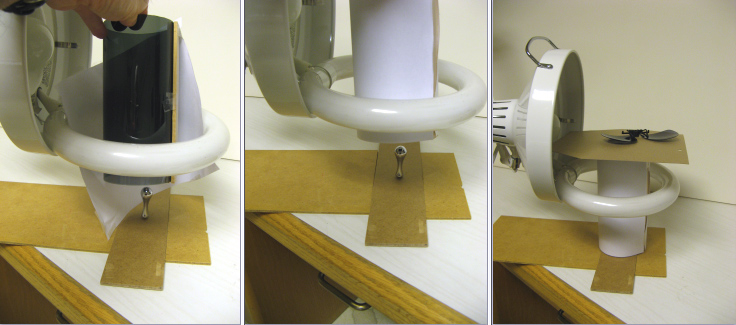
Test Series 1 (small diameter, flat, diffused polarized source):
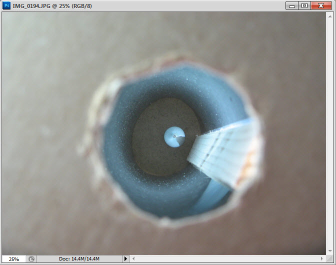
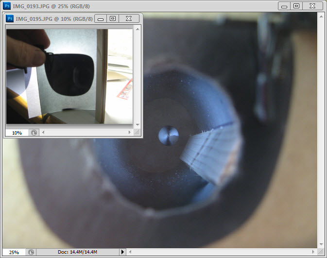
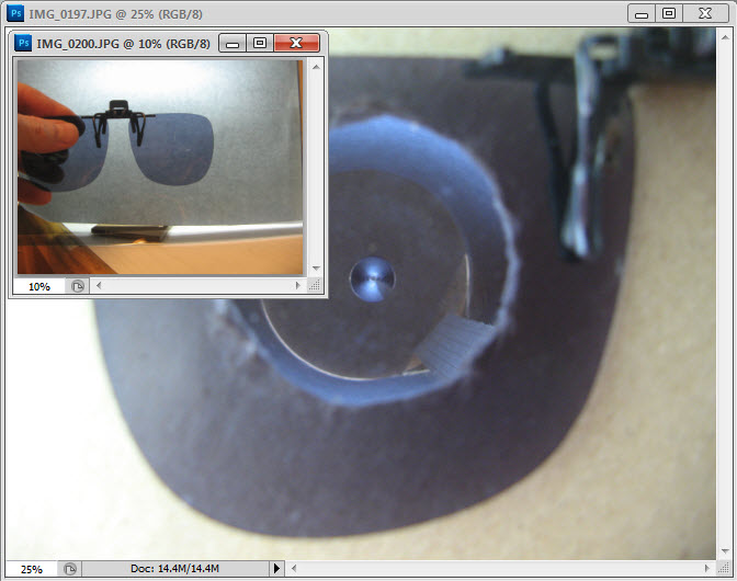
Because of the tendency of a broad light source, which is shaped into a sphere, arc or tube surrounding the subject to reflect or back-scatter light from the primary beam back to onto the subject from adjacent walls, I simplified the lighting arrangement in this test by using a small, flat, circular (40mm diameter) collimated light source (LED flashlight). The flashlight had diffusion film first, followed by a polarizing film taped over the front reflector. The plane of polarization was determined and marked on the film by reflecting the beam off of a dielectric (glass) surface at near Brewster’s angle. At minimum reflection, the polarization of the film should be orthogonal to the surface of the glass. This was also verified to be consistent with the “polarized sunglasses” method mentioned by AndrewC.

The polarized light source was used as a “probe” to determine the reflections off of the subjects at different incidence angles and planes of polarization of the source and rotations of analyzer polarizing filter. Each pair of images were taken with the light source coming from either the front left or right of the subject, at approximately 45 degrees from the x,y,z axes The plane of polarization for each L, R pair was maintained at the same angle relative to the optical axis of the lens as the source was moved from left to right. Exposure was kept the same for each set.

In these first two images, the source polarization angle was arranged parallel to the optical axis. In the first image, the analyzer was rotated to achieve maximum extinction and remained in that position for the second image.

Image
Image


In this pair, the analyzer was in the same rotation as the first pair, but the source was rotated to be orthogonal (perpendicular) to the optical axis.
Image
Image


Here the analyzer was rotated 90 degrees, with the source parallel.
Image
Image


Source moved further away from subject simulating more of a point source, max extinction point.
Image


Test Series 2 (broad, flat, diffused polarized source)
The light source in this test was made from a rectangular (150mm x 210mm) strongly-diffusing plastic plate (stock part from a Nikon R1C1 flash kit) covered with polarizing film on the side facing the subject. The source was positioned directly over the subjects, as close as possible (just out of frame). The analyzer filter was rotated to the angle shown in the caption. (Edit: This better shows Rik’s “fan blade” effect.)


Centered (0 degrees)
Image


30 degrees left
Image


30 degrees right
Image


180 degrees
Image


Conclusions
The results are consistent with Rik’s observations in the current thread and in previous threads. In terms of using cross polarizers to cancel or reduce specular reflections, the key factors are the degree of polarization and polarization angle of the light as reflected off of the subject relative to the plane of polarization of the polarizing filter (analyzer) on the lens. For a curved surface like the spheres used here, the plane of polarization rotates depending on the angle of the reflected beam, thus making it impossible to completely cancel the reflection from a diffuse polarized source, if it covers a wide angle relative to the (curved) subject. However, it is possible to largely cancel the specular reflection from a point polarized source. I didn’t show it here; but it is also possible to substantially reduce specular reflections from an arbitrary single flat surface, under the conditions tested here. Perhaps this may help to explain why Charles was able to almost completely eliminate the reflections on his mostly flat shield bug?:

http://www.photomacrography.net/forum/v ... hp?t=11254

But is if you look closely at this image, I think it’s possible to see the “fan blade” effect in some of the reflections from the beads of moisture on the insect.

Another effect that is apparent in these tests is that the fan blade does indeed rotate depending on whether the source polarization is parallel or orthogonal to the optical axis. I would guess that this is why Andrew’s images appear different in these two cases.

As is often the case in doing these tests, some (possibly new, probably not) ideas have “spontaneously generated” in my feeble mind. So once again, I’ll throw them at the preverbal wall to see if they stick. In Andrew’s early thread on this topic, Morfa (John) suggested making a box out of polarizing material in which the sides were rotated to compensate for the inherent rotation of the source or sources as reflected off of the subject from different directions. Based on the above tests, I think this idea has merit---at least for specific subjects.

What if we take this idea to the next logical step and cut strips or patches of polarizing film and assemble them into the desired shape (say bonded to the inside of a diffusion film) so that the plane of polarization is oriented to the correct angle to compensate for reflection angle off each part of the subject? Taken to the extreme (this may not be possible to manufacture), what if a polarizing film could be made (perhaps formed into a sphere), where the plane of polarization changes around the sphere so that the subject is illuminated by polarized light such that the reflections can be canceled with a polarizer on the camera?

One obvious issue with this concept---while I believe this might be useful for symmetrical surfaces like spheres, I can foresee that there might be problems with other arbitrary shapes or mixtures of shapes. So in the end, there may be no perfect solution.

Edit: While I've got the stage setup for these tests, I just took a quick look (using Live View) at one of my favorite subjects, a jumping spider (P. johnsoni). Illuminated with the polarized flashlight held at close distance and rotating the polarizing filter on the lens I could make the reflections in the large eyes look like horizontal or vertical pupils. Ya know, cat eyes on a jumping spider just don't look right! :D
Bob in Orange County, CA

Bob^3
Posts: 287
Joined: Sun Jan 17, 2010 1:12 pm
Location: Orange County, California

Post by Bob^3 »

AndrewC wrote:For reference my favourite of this subject is the HDR stacked stack of it with no polarizer filter as shown here.
Andrew, I also think that is a much more natural and pleasing image than the cross polarizer images. And also an excellent application of HDR methods! 8)
Bob in Orange County, CA

rjlittlefield
Site Admin
Posts: 23626
Joined: Tue Aug 01, 2006 8:34 am
Location: Richland, Washington State, USA
Contact:

Post by rjlittlefield »

Bob, thanks for the excellent images and analysis. I will have to read through all that a few times to be sure I have gotten everything.

My setup was quite a bit simpler even than yours. I think that makes the effects more obvious, and the setup itself may be of interest. Anyway, here's my setup and results.

Illumination is with a fluorescent ring tube, partially unclipped from a desk lamp. Polarizing sheet material is wrapped into a cylinder, which is wrapped with paper for diffusing, and the whole cylinder is set over a chrome "sphere" (a handle borrowed from my stacking screw table). On top of the diffusing/polarizing cylinder is a hunk of cardboard with a hole in the middle of it, and over the hole is a pair of ordinary clip-on sunglasses. A compact digital camera (not shown) shoots through the hole in the cardboard, with and without the sunglasses in place.

Image

Without the sunglasses and with the fluorescent tube turned on, here is what the camera sees. In this case the illumination is quite diffuse, illuminating the chrome sphere almost uniformly except for one dark slice at lower right caused by the strip of wood that keeps the polarizing sheet aligned, and one slightly dim slice at upper left caused by the socket of the lamp.

Image

With the sunglasses in place, here is what the camera sees. Notice that there is a pair of very dark "fan blades", whose orientation varies to match the axis of polarization for the cylinder.

Polarizing sheet wrapped so that the cylinder axis is "crossed polarizers".

Image


Polarizing sheet wrapped so that the cylinder axis is "parallel polarizers".

Image

By the way, when I wrote earlier that "Rotating either axis of polarization simply makes the fan rotate", I think that's true only for the two simple orientations where the axis of polarization either runs straight along the cylinder or straight around it. If the axis of polarization is slanted so that it spirals along the cylinder, then I think the pattern on the sphere may change from being a two-bladed fan to being some weird spiral of its own. But I haven't thought really hard about that one, or tested it, and I'm happy to leave it to someone else. :)

--Rik

AndrewC
Posts: 1436
Joined: Thu Feb 14, 2008 10:05 am
Location: Belgium
Contact:

Post by AndrewC »

Bob^3 wrote:.....

...

One obvious issue with this concept---while I believe this might be useful for symmetrical surfaces like spheres, I can foresee that there might be problems with other arbitrary shapes or mixtures of shapes. So in the end, there may be no perfect solution.

...
Just need to breed some mutant spherical beetles ! Seriously, though - polarizers, crossed or not, are just another tool to play with and sometimes come up trumps and sometimes not. Bottom line is that it is always worth experimenting ... in the spirit of which I've found a $10 parabolic reflecting dish with a 35-40mm focus distance - perfect for an Oly 38mm, I'll start a thread on it later.

Andrew
rgds, Andrew

"Is that an accurate dictionary ? Charlie Eppes

Bob^3
Posts: 287
Joined: Sun Jan 17, 2010 1:12 pm
Location: Orange County, California

Post by Bob^3 »

My setup was quite a bit simpler even than yours. I think that makes the effects more obvious, and the setup itself may be of interest.
Yes, and yours better shows the full effect in the case of a full-tube diffused polarizer configuration.
By the way, when I wrote earlier that "Rotating either axis of polarization simply makes the fan rotate", I think that's true only for the two simple orientations where the axis of polarization either runs straight along the cylinder or straight around it. If the axis of polarization is slanted so that it spirals along the cylinder, then I think the pattern on the sphere may change from being a two-bladed fan to being some weird spiral of its own.
I was intrigued enough by this concept that I ran a quick visual check using a diffused polarizing tube similar to yours. With the polarizing film wound in a 45 degree spiral, the "fan blade" looks the same as yours at the top (center) of the chrome sphere and is also shaped like a dumbbell, but the wide ends of the dumbbell twist into a partial spiral at the edges of the sphere---like looking at the working end of a spiral drill bit.
Bob in Orange County, CA

Post Reply Previous topicNext topic