Of course I couldn't resist taking it apart to learn how it was supposed to work, and why it no longer did.
Here are the answers.
First, half of the breaker in its normal ON configuration:
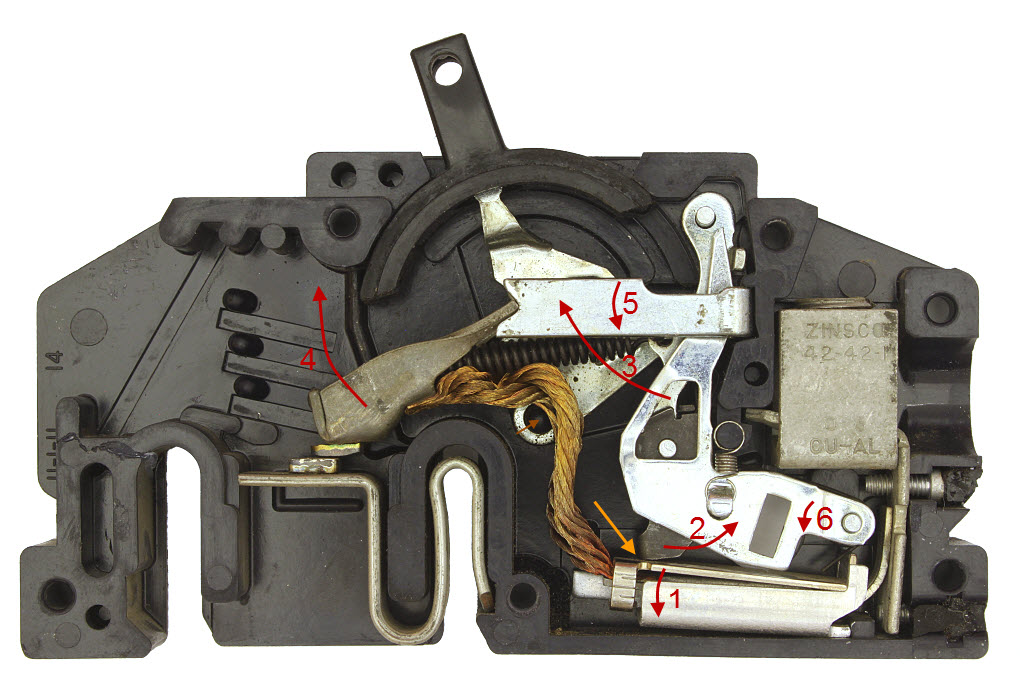
The arrows indicate key points of action.
The orange arrow points to arguably the most important location in the whole breaker -- the place where the tripping action gets triggered. What happens is that under continuous slight overload, the thin bright plate below the orange arrow rotates downward, as shown by the bottom red arrow (1), driven by heating of a bimetallic strip. Or under instantaneous extreme overload such as a short circuit, it rotates downward driven by a magnetic field from the large current.
In either case, movement of the thin bright plate causes it to release the dark gray catch mechanism just above it, which is spring loaded to rotate in the direction of the middle red arrow (2). This rotation in turn releases yet a stronger spring-loaded lever, which rotates up as shown by the upper red arrow (3), carrying with it the end of the spring that holds the electrical contact in place. When that last lever rotates far enough, it brings the spring past center of the pivot that holds the electrical contact bar, and the bar then springs suddenly upward (4), breaking the circuit. (!!)
Simultaneously,the pivot of the electrical connection bar moves downward, driven by the same spring, carrying with it the bright U-shaped bar (5), which is connected to the external handle by a couple of little bent tabs on the farthest back metal plate. Voila, the breaker now indicates "Tripped".
Likewise, the release of the heavy spring-loaded bar (3) forces the bright bar with the fancy cutouts to rotate slightly downward (6), thereby jamming the thin bright trigger plate plate down solid and simultaneously forcing its mate on the other electric phase to do the same thing, thereby cutting off both phases at the same time and leaving both handles in the Tripped position.
To reset the breaker, you first push the handle firmly to its OFF position, which pushes all the mechanics back into place and re-engages the trip latch indicated by the orange arrow. Then you push the handle back to the ON position, which slightly repositions things so that the electrical contact goes smashing closed again under pressure from its really very strong spring.
This process is illustrated in the following animations, which show transitions from ON to Tripped, Tripped to OFF (and reset), and finally OFF to ON.
If you'd like more details on operation of the beast, it's described in fair detail in US Patent #2,502,537, currently accessible HERE.
Oh yeah... What made the breaker fail? Go back to the first picture and look for the little brown arrow just under the bend in the copper braid. That points to a pivot pin, molded into the plastic of the case. The pin broke off the other breaker of this pair, leaving no way to reset the breaker when it tripped. $178 for a new breaker, because a piece of plastic cracked. Isn't technology wonderful? Ah well, it was an old breaker, time to die anyway...
--Rik