Help needed with DIY manual output control for Vivitar 283

Have questions about the equipment used for macro- or micro- photography? Post those questions in this forum.

Moderators: rjlittlefield, ChrisR, Chris S., Pau

Planapo
Posts: 1583
Joined: Tue Nov 07, 2006 2:33 am
Location: Germany, in the United States of Europe

Help needed with DIY manual output control for Vivitar 283

Post by Planapo »

I'm planning to use two Vivitar 283 flashlights for macro work, mainly for use indoors. These flashlights have the advantage that they possess a plug on the front that allows for easy access in order to control their output manually, The output can be altered in fine steps either with an accessory part from Vivitar that is discontinued, but can occasionally be found used. Or one is as skilled as Charlie Krebs and builds such a control unit oneself that allows for even finer tuning.

Now, from the information that Charlie kindly provides on his website, I think I've understood how it is done in principle: Exchange the photo resistor of the the sensor against two variable resistors (I supose potentiometers) that can be manually adjusted with the switch wheels, . And Charlie gives the Ohm values that are needed. Now, that's for the theory.

But as I am not much experienced in practical electronics tinkering: What purchasable parts exactly are in Charlie's black box with the switch wheels? What do I have to order from the electronic store (e. g. www.reichelt.de, I also have their printed catalogue at hand :smt017 8-[ :smt100), and how does it have to be soldered together to fit and work in the black box?

As I am thinking here is enough techy engineering folks around that can help me with this question, I thought there is no need for me to 'bother' Charlie directly, who seems still busy with his move. So please could you tell me what parts to get and how to fit them together to obtain such a nice control unit à la Charlie?

Thanks much for your, as always, highly appreciated help, boys!

--Betty

NikonUser
Posts: 2693
Joined: Thu Sep 04, 2008 2:03 am
Location: southern New Brunswick, Canada

Post by NikonUser »

I assume that at least 1 flash must be off-camera, perhaps both are.
An alternate control is to use them at full power and simply increase/decrease the distance between flash and diffuser/subject.

If one flash is on-camera its output can be controlled by varying layers of tissue paper - which also serve as great diffusers (one of Rik's techniques I believe).

I sometimes use an ancient Nikon flash as an auxillary light source and control its effect by varying the distance between it and the diffuser.

But I agree, Charlie's system is a much better option.
NU.
student of entomology
Quote – Holmes on ‘Entomology’
” I suppose you are an entomologist ? “
” Not quite so ambitious as that, sir. I should like to put my eyes on the individual entitled to that name.
No man can be truly called an entomologist,
sir; the subject is too vast for any single human intelligence to grasp.”
Oliver Wendell Holmes, Sr
The Poet at the Breakfast Table.

Nikon camera, lenses and objectives
Olympus microscope and objectives

rjlittlefield
Site Admin
Posts: 23625
Joined: Tue Aug 01, 2006 8:34 am
Location: Richland, Washington State, USA
Contact:

Post by rjlittlefield »

A sketched schematic is on its way to Betty by email. Let's hope I drew it correctly!

As for picking out components in that catalog, I don't speak the language well enough to search, so I'll let somebody else handle that part.

--Rik

Charles Krebs
Posts: 5865
Joined: Tue Aug 01, 2006 8:02 pm
Location: Issaquah, WA USA
Contact:

Post by Charles Krebs »

Hi Betty...

I used two "single pole, 12 position switches" like the one seen here:
http://shop.willyselectronics.com/brows ... ,4798.html

The resistance values were then wired using inexpensive 1/4 watt resistors. I had initially made up a control using "variable resistors" (potentiometers) but found that I greatly preferred having discrete values at 1/2 stop intervals.

It's really quite simple... all you need is very rudimentary soldering skills. The idea is simply to "loop" the resistance value through the two flash contacts shown on the web page (and it is easy to modify a standard sensor "plug" as shown on that web page). Here's a simplified sketch of how it was done. This sketch shows a single resistor but in most cases you'll need more than one resistor in series to get close to the posted values:

Image

I used two switches, and "toggled" between them in order to get enough positions to do half stops from full power to -8 stops. I suppose it could be done differently, but for the microscope I found this was convenient as the upper switch could be set for the approximate light level needed for DIC, and the lower one set for the approximate level for brightfield.
...who seems still busy with his move
Unfortunately the case. I cruise through here ever other day or so, but I doubt I'll have my microscopes and tabletop setups operational before late summer. ](*,)

Planapo
Posts: 1583
Joined: Tue Nov 07, 2006 2:33 am
Location: Germany, in the United States of Europe

Post by Planapo »

Good to know I can count on my overseas buddies! Hey there, you're gorgeous! :smt023

Thanks NU, I had thought about that muffle/distance approach but with the limited space and all the other clutter on my 'table top', Charlie's control unit is just too tempting.

Hi Charlie, good to see you! Sorry to hear that you still haven't full access to your equipment again. But then, as long as you will appear in the right moment when I am in desperate need for advice, I think I can handle the hard time bereft of Krebs-manufactured eye-candy till late summer. :wink:
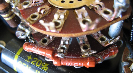
With both blueprints, yours together with the one Rik has sent me (Thanks again, Rik!), I get a good picture of what to buy and how to wire it up. Ah, fixed Rs that makes sense, I had already been wondering about the even spacing on the scale/dial of the two rotary switches.

Here's the shopping list I have compiled from the catalogue

1.
As for the Rs, they'd be available either as
"coal-layer-resistors" (Kohleschicht-Widerstände)
http://www.reichelt.de/?;ACTION=3;LA=3; ... d845160ee4

or "metal-layer-resistors" (Metallschicht-Widerstände
http://www.reichelt.de/?;ACTION=3;LA=44 ... d845160ee4

2.
the "Rotary Switch Shorting 1 Pole 12 Position Solder" that Charlie has shown above is a
"Stufen-Drehschalter 1 Pol 12 Stellungen Lötkontakt"
http://www.reichelt.de/?;ACTION=3;LA=44 ... ad3a9143e2

3.
for the spdt (single pole double-throw) toggle switch (jeez, boys you're teaching me weird vocabulary :))
I found this Sub-Miniatur-Schalter 1-polig, the triple Ein/Aus/Ein (On/Off/On), or I think I could take just the double Ein-Ein (On/On)
http://www.reichelt.de/?;ACTION=3;LA=3; ... ad3a9143e2

4.
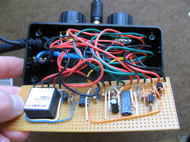
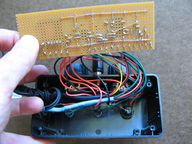
Charlie's sketch above suggests a kind of board on which the parts are fixed. On what kind of board (circuit board or strip board (right word?)) should I solder the things together. I found these:
http://www.reichelt.de/?;ACTION=3;LA=44 ... d845160ee4
Or am I totally wrong with how the resistors get fixed and connected within the housing? There are Cu-ligaments (Do you read me?) inside some of such boards, and wholes where the wire ends of the resistors get plugged in, right?
Or should I get a nonconducting board, drill little wholes in that to place the resistors, solder them together and to the switches with enamel insulated Cu-wire, and eventually fix the loose wire with hot glue to the board?
And what kind of insulated Cu-wire of what diameter do I need to connect the parts? I found these clear enamel insulated Cu wires, that can be soldered:
http://www.reichelt.de/?;ACTION=3;LA=44 ... ad3a9143e2

5.
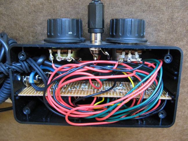
For the housing/box: estimating the size from the photo of Charlies box, I guess a 122 mmx 80 mm x 57 mm housing should do, like this one
http://www.reichelt.de/?ACTION=3;ARTICL ... ad3a9143e2
or this one with an aluminium lid in 110 mm x 70 mm x 49 mm
http://www.reichelt.de/?;ACTION=3;LA=44 ... ad3a9143e2

Sorry for the silly questions, the little bit of electronics I've learned, twas all theoretical, I never did something like this before in practice, but am looking forward to create such a device myself that hopefully will work and do a usefull job. Did I get anything wrong? Any suggestions on what kind of board I should solder the resistors together? And what size of board and housing I should take that I don't end up with a board of too small size where not all of the needed Rs fit on.

Thanks much again for your help, pals!

--Betty :D

edit: fixed bad links to resistors
edit: and another one to the board
Last edited by Planapo on Sat May 30, 2009 11:53 pm, edited 2 times in total.

rjlittlefield
Site Admin
Posts: 23625
Joined: Tue Aug 01, 2006 8:34 am
Location: Richland, Washington State, USA
Contact:

Post by rjlittlefield »

Betty,

By your numbers...

1. Either type of resistor will work fine. Oddly, both of your links just show me pages with the catalog's framework, no components showing.

2. The switch appears correct, and that link works fine.

3. I would probably go with the Ein-Ein. The middle position of Ein-Aus-Ein just gives one more thing to set wrong. (I have much practice setting things wrong!)

4. If a board is required, generally I work with a bare insulating sheet -- many holes, but either no copper at all plated on the board, or just little copper rings around the holes. For insulated wiring, I would not use clear enameled wire -- it is too hard to be sure that the insulation is intact, and even when it is, all the wires look alike! I prefer to use color-coded plastic insulation. Solid conductor telephone or network cabling can be disassembled to yield 8 distinct color patterns.

But this controller might be easiest to construct by soldering resistors directly to the switch contacts, no board required. You will have to decide based on the physical sizes of things.

Here are some pictures that may give ideas:

From an old multimeter, resistors wired directly to rotary switches:

Image

An LED controller, circuit on board with flexible wiring to controls and connectors.

Image

Image

Image

Hope this helps!

--Rik

Planapo
Posts: 1583
Joined: Tue Nov 07, 2006 2:33 am
Location: Germany, in the United States of Europe

Post by Planapo »

Rik, Thanks much for these instructive photos and comments!

They give me a very good idea, what I shall take as board, wire and what it should all look like in the end!

I have fixed the bad links above.

--Betty :D

Harold Gough
Posts: 5786
Joined: Sun Mar 09, 2008 2:17 am
Location: Reading, Berkshire, England

Re: Help needed with DIY manual output control for Vivitar 2

Post by Harold Gough »

Planapo wrote:I'm planning to use two Vivitar 283 flashlights for macro work, mainly for use indoors. These flashlights have the advantage that they possess a plug on the front that allows for easy access in order to control their output manually, The output can be altered in fine steps either with an accessory part from Vivitar that is discontinued, but can occasionally be found used.
I have my 283 in my hand and hope that some of the following may be helpful for standard (not DIY) operation.

The device which plugs in the front is called an "auto thyristor". It can also be used off the camera on a "remote sensor lead" (or some similar name) which plugs in the front of the gun.

There is M (manual setting) and yellow, red, blue and purple.

On the side of my gun, I have attached a label:

" Auto range all films: Yellow 5-43ft, Red 4-30ft, Blue 2-15ft, Purple 2-11ft, set aperture for distance". The last instruction refers the user to the dial on the gun, to be set for film speed.

Whether the gun can be adjusted " in fine steps" is debatable.

Harold
My images are a medium for sharing some of my experiences: they are not me.

Planapo
Posts: 1583
Joined: Tue Nov 07, 2006 2:33 am
Location: Germany, in the United States of Europe

Post by Planapo »

Harold,

Harold Gough wrote:
The device which plugs in the front is called an "auto thyristor"
I think the device that plugs in the front is just the sensor (though unfortunately it's labelled 'auto thyristor' in some 283 units, in others just sensor). This sensor should pricipally be a photo resistor with gray filters that more or less shade the photo resistor when the knob is turned, thus altering the flashlight output with the different settings you mentioned. I don't think that the 283's thyristor is built in the sensor unit itself. As I get it, the thyristor (a semiconductor device) in this case helps the 283 save energy with the capacitor operation, thus recylce faster and allowing for more flashes to be fired per battery load.

Harold Gough wrote:
Whether the gun can be adjusted " in fine steps" is debatable.
It's not. The 283's output can be adjusted in finer steps either with Vivitar's Variopower VP-1 module that replaces the sensor, which in your unit seems labelled "auto thyristor (another hint that the thyristor is built in the flash unit itself), or, can be adjusted in even finer steps with a custom made controller that we are discussing in this 'string'.

--Betty

edit: "don't think that the 283's thyristor is built in the flash unit itself" edited to "don't think that the 283's thyristor is built in the sensor unit itself", which I had meant from the beginning, as one can see from the sentence in brackets in the last paragraph.
Last edited by Planapo on Mon Jun 01, 2009 6:21 am, edited 1 time in total.

g4lab
Posts: 1437
Joined: Fri May 23, 2008 11:07 am

Post by g4lab »

Here
is a lot of information on the Vivitar 283 strobe.

rjlittlefield
Site Admin
Posts: 23625
Joined: Tue Aug 01, 2006 8:34 am
Location: Richland, Washington State, USA
Contact:

Post by rjlittlefield »

The reference given by g4lab is very readable, but it never explains what a "thyristor" is and what is meant to make one "auto".

A thyristor is a high voltage semiconductor switching element. In flashes, thyristors are used to switch current through the flashtube, on to start the flash and off to stop it. These devices are definitely located within the flash unit, probably on that little board called the "flash trigger circuit".

The part about "auto" just means that the flash unit decides when to turn off the flash based on how much light is reflected back from the environment. If you are shooting a scene relatively close, then more light will get reflected back and the flash will turn off in a shorter time.

The fact that the plug-in sensor module is labeled "auto thyristor" is a quirk of the labeling. That module contains no thyristor. Switching will be done by the one in the flash unit no matter whether the flash is controlled by reflected light via the plug-in module, or by a fixed or adjustable resistor like Charlie's controller.

--Rik

Charles Krebs
Posts: 5865
Joined: Tue Aug 01, 2006 8:02 pm
Location: Issaquah, WA USA
Contact:

Post by Charles Krebs »

FWIW... although not linked or mentioned on my site, I do have a complete Vivitar 283 Service Manual up here:
http://krebsmicro.com/283manual/vivitar_283.pdf

Planapo
Posts: 1583
Joined: Tue Nov 07, 2006 2:33 am
Location: Germany, in the United States of Europe

Post by Planapo »

Thanks for making this document accessible, Charlie. Downloaded already! :D

--Betty

NikonUser
Posts: 2693
Joined: Thu Sep 04, 2008 2:03 am
Location: southern New Brunswick, Canada

Post by NikonUser »

I'm following this thread; being electronically challenged I find the idea of moving/muting the flash getting more appealing by the day!
NU.
student of entomology
Quote – Holmes on ‘Entomology’
” I suppose you are an entomologist ? “
” Not quite so ambitious as that, sir. I should like to put my eyes on the individual entitled to that name.
No man can be truly called an entomologist,
sir; the subject is too vast for any single human intelligence to grasp.”
Oliver Wendell Holmes, Sr
The Poet at the Breakfast Table.

Nikon camera, lenses and objectives
Olympus microscope and objectives

Harold Gough
Posts: 5786
Joined: Sun Mar 09, 2008 2:17 am
Location: Reading, Berkshire, England

Post by Harold Gough »

Planapo wrote: The 283's output can be adjusted in finer steps either with Vivitar's Variopower VP-1 module that replaces the sensor, which in your unit seems labelled "auto thyristor
Betty,

Thanks for that. Having used my 283 (in a manual, calibrated set-up, which I am thinking of recalibrating for some applications) almost full-time for macro in the mid 1980s, I was unaware of this additional device. Of course, we had few sources of information in those days, modern websites having revolutionised our access. Having said that, I don't see myself using the fine-tuning, as I now have a full range of Olympus OM flash units

Harold
My images are a medium for sharing some of my experiences: they are not me.

Post Reply Previous topicNext topic