Revisiting the yucca moth: stacked macro vs SEM

A forum to ask questions, post setups, and generally discuss anything having to do with photomacrography and photomicroscopy.

Moderators: rjlittlefield, ChrisR, Chris S., Pau

rjlittlefield
Site Admin
Posts: 23599
Joined: Tue Aug 01, 2006 8:34 am
Location: Richland, Washington State, USA
Contact:

Revisiting the yucca moth: stacked macro vs SEM

Post by rjlittlefield »

Periodically, somebody writes that focus-stacked optical images look an awful lot like scanning electron micrographs, except in full color.

Shucks, I've written that myself. :wink:

I thought you might be interested in a direct illustration of that idea.

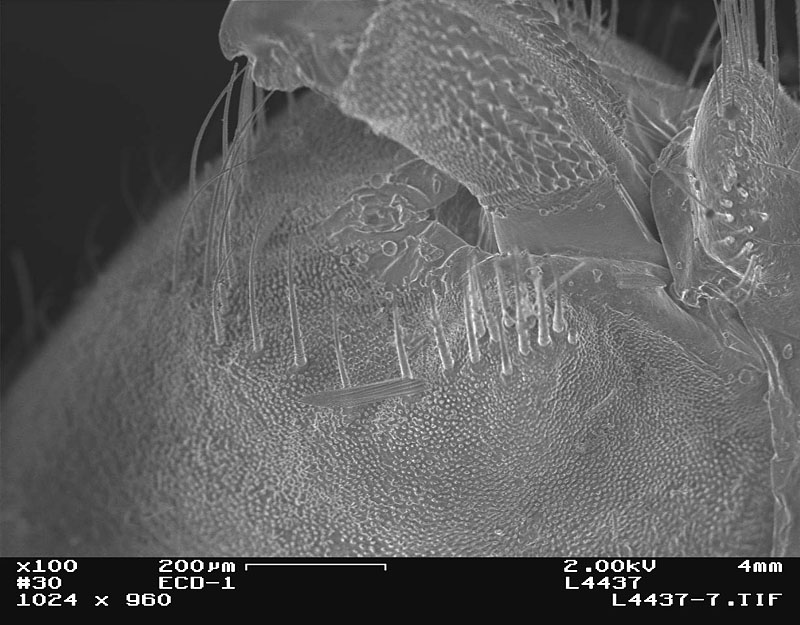
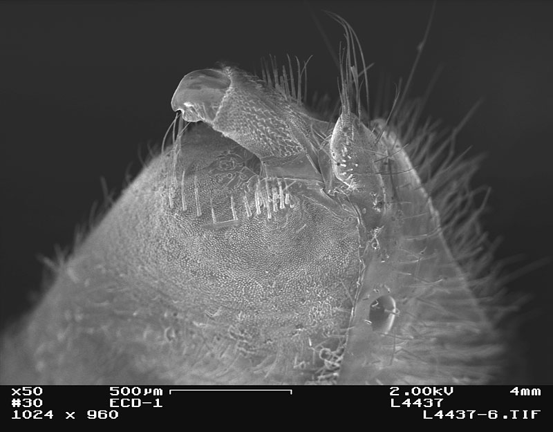
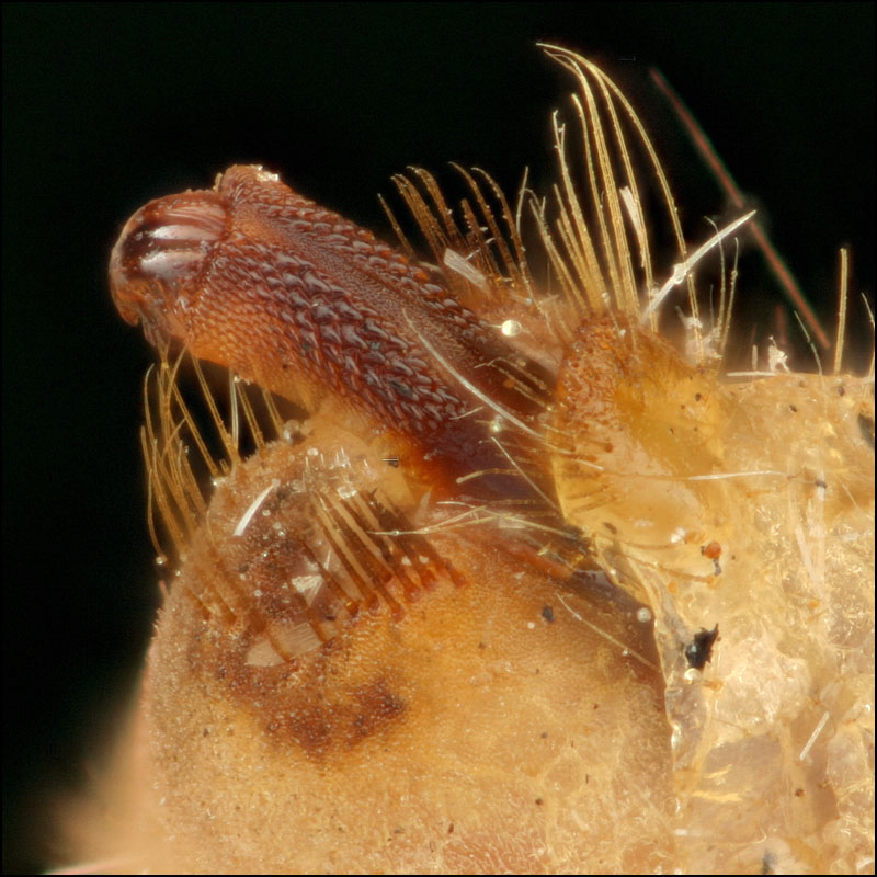
What we have here are three pictures of the tail end of a yucca moth, two shot with an SEM at the lab where I work, and one as an optical stack on my kitchen table, using a macro lens on bellows.

Background and technical information is given here. The only new snippet is that this particular stacked image was created this evening using TuFuse Pro 0.9.3, with no manual retouching.

In the stacked image, you can see a bit of the common "show through" visibility error, in this case where background bristles appear to be visible behind a semi-transparent foreground structure, when in fact the foreground structure is completely opaque and the background bristles were actually seen by a wide-aperture lens looking around the foreground structure while focused on the background.

--Rik

Image

Image

Image

Planapo
Posts: 1581
Joined: Tue Nov 07, 2006 2:33 am
Location: Germany, in the United States of Europe

Post by Planapo »

Very interesting to have them both side by side for a direct comparison.
Thanks for taking the time and putting this together, Rik!

--Betty :D

lauriek
Posts: 2402
Joined: Sun Nov 25, 2007 6:57 am
Location: South East UK
Contact:

Post by lauriek »

You're not helping sell that SEM here!! ;)

rjlittlefield
Site Admin
Posts: 23599
Joined: Tue Aug 01, 2006 8:34 am
Location: Richland, Washington State, USA
Contact:

Post by rjlittlefield »

lauriek wrote:You're not helping sell that SEM here!! ;)
Well, what's shown above is the region where optical focus stacking overlaps SEM imaging.

One of the reasons that SEMs are much loved is because they have great DOF at modest magnifications. That's because the short wavelength of electrons lets the SEMs run at f/1000 or so, while still delivering much greater resolution than optical setups.

What focus stacking does is to cancel out the DOF advantage of the SEMs, at least when one is paying attention only to the in-focus regions.

But whenever you're using light at a distance, you're still subject to the problem of limited resolution due to wavelength. So really all this focus stacking stuff does is to change the envelope a little, pushing optical methods into a little bit of the space that is otherwise clearly occupied by SEMs.

Here is a closer view of the bristles. Impossible with optical, easy with SEM.

--Rik

Image

Graham Stabler
Posts: 209
Joined: Thu Dec 20, 2007 11:22 am
Location: Swindon, UK

Post by Graham Stabler »

What strikes me is the greater information content in the macro images, you can often map the hardness of parts of the insect to the darkness of it, something you just cant see in the SEM images.

rjlittlefield
Site Admin
Posts: 23599
Joined: Tue Aug 01, 2006 8:34 am
Location: Richland, Washington State, USA
Contact:

Post by rjlittlefield »

Yep. A flashing backlight reveals even more, if you can keep the strobe-induced epilepsy from kicking in.

This looks like some weird falcon's head, but it's actually the working end of the ovipositor, seen in profile. This was shot from the backside of the oblique view that's shown above.

--Rik

Image

Graham Stabler
Posts: 209
Joined: Thu Dec 20, 2007 11:22 am
Location: Swindon, UK

Post by Graham Stabler »

It looks like you are getting some illumination through the sample when back lit. The cuticle is amazingly transparent, I found that when looking at some resin embedded samples with a strong back light it was light having x-ray vision, only the most chitinized parts were opaque.

With some bleaching and optical matching fluid this has been taken to the extreme (note free download):

http://www.plosone.org/article/info%3Ad ... ne.0000834

It is basically optical CT (computed tomography), an invention used for looking at radiation dosing in special gels originally, then reinvented and renamed optical projection tomography and used on mouse embryos. I have been doing some myself but only on small parts and without bleaching so with limited success, I found this paper last week.

Graham

rjlittlefield
Site Admin
Posts: 23599
Joined: Tue Aug 01, 2006 8:34 am
Location: Richland, Washington State, USA
Contact:

Post by rjlittlefield »

Graham Stabler wrote:It looks like you are getting some illumination through the sample when back lit.
Yes, that was the point. From front lighting alone, you would get the feeling that the structure was opaque, but by adding the backlight it became apparent that it was actually somewhat transparent, with wide variation between parts. This is all qualitative, of course, but I thought it might be useful as part of the specimen record.

Thanks for the link to the article on optical projection tomography. That's a technology that I've been only vaguely aware of. I notice that the resolution isn't very good -- the article says only 5-10 microns per pixel, where my yucca moth image is about 0.8 micron per pixel and the stacks we do with microscope objectives are a lot better than that. Do you know what causes the limited resolution of OPT? If it's due to the low NA of a nearly collimated projection beam, then perhaps there's an opportunity to merge stacking and OPT to crank the resolution up. (Let's see, 400 angles by 50 images per stack...yep, definitely want to automate that.)

--Rik

Edited to add: BTW, the "backlighting" for the yucca moth was actually accomplished by just inserting a white piece of paper behind the moth, between it and the light trap that I used for the black background. Exposure and illumination were identical, so any brightening of the subject is due to light coming through the subject, except along the very edges where there is some additional reflection from the background paper.

Graham Stabler
Posts: 209
Joined: Thu Dec 20, 2007 11:22 am
Location: Swindon, UK

Post by Graham Stabler »

Rik,

I'm not sure that the 10um is a limitation of the technique rather a limitation of that particular set up.

Unlike x-rays you can't expect light to travel in straight lines through the sample perfectly, otherwise you could use a focussed source and a detector with no lenses at all (although that has been done and might be worth another shot, especially with a full field sensor and an objective as a focusser). That is all these x-ray microCT scanners are, a focussed x-ray source, a stepper motor for sample rotation and an x-ray camera, you can build your own from Hamamatsu parts but it is still $$$.

For optical CT you use the "tube" of rays formed at the focus of the lens that extends over the DOF as a means of taking a line integral through the sample. Illumination is normally just diffuse, filling the volume completely. Depending on sample size you may need quite a good DOF (at least half sample depth if you do 360 degree reconstruction) so that can limit resolution.

As far as stacking goes I have had the same though, have a small DOF and then scan it through. But I think you would process by a simple summation. Only need half a revolution if your scan goes through the entire sample too.

Reconstruction is pretty easy, I used the most basic type which is just a bit of trig, you back propagate each projection through a volume and let the result build up. The only maths is based on the angle the projection is at compared to your resulting volume. For speed you can go to FFTs but as yet I'm happy to wait.

Great downloadable book: http://www.slaney.org/pct/pct-toc.html

Chap3 equation 1 is all you need!!

Graham

Harold Gough
Posts: 5786
Joined: Sun Mar 09, 2008 2:17 am
Location: Reading, Berkshire, England

Post by Harold Gough »

rjlittlefield wrote:
lauriek wrote: One of the reasons that SEMs are much loved is because they have great DOF at modest magnifications. That's because the short wavelength of electrons lets the SEMs run at f/1000 or so, while still delivering much greater resolution than optical setups.

--Rik
Is "wavelength" the issue here? I have always understood that it was a scanning beam of electrons. Having said that, it must be some 20-30 years since I was involved in work where it was relevant.

Harold
My images are a medium for sharing some of my experiences: they are not me.

Planapo
Posts: 1581
Joined: Tue Nov 07, 2006 2:33 am
Location: Germany, in the United States of Europe

Post by Planapo »

Harold,

Wavelength is an issue when it comes to diffraction. And there are "lenses" with apertures in an SEM where the "beam" of electrons is focussed through.

The wavelength of the (moving) electron (or generally a moving particle) is lambda= h/p
(after De Broglie; remember wave-particle duality)

and with a short wavelength of appropriately accelerated electrons diffraction isn´t an issue with - compared to photography with visible light - very small apertures required for large DOF.

--Betty

rjlittlefield
Site Admin
Posts: 23599
Joined: Tue Aug 01, 2006 8:34 am
Location: Richland, Washington State, USA
Contact:

Post by rjlittlefield »

Harold,

Google "wavelength of an electron" (with the quotes) and you will be quickly directed to a Wikipedia article on Electron Diffraction that explains that everything has a wavelength, which depends on its momentum, which depends on its rest mass and its velocity.

For an electron in an SEM, the article quotes a wavelength lambda of typically 12.3 pico-meters (12.3*10^(-12) meters).

That sounds like an insignificant number.

But when you run it through an f/1000 aperture, and apply the standard formulas for resolution that NA = 1/(2*fnumber) and resolution = lambda/(2*NA) [ref], that electron wavelength of lambda = 12.3 picometers turns into subject resolution of 12.3 nm = 0.0123 micron.

That's comfortably smaller than the best optical resolution of around 0.2-0.3 micron, so indeed the wavelength of an electron is not an issue when working at only f/1000 and at magnifications similar to what you would use in optical imaging.

However, it is also uncomfortably larger than the best SEM resolutions of 1-5 nm that are quoted elsewhere. What this tells us is that for the higher resolution scopes electron wavelength is an issue. It also tells us that they're not operating at f/1000, but probably more like f/100, giving again rather limited DOF.

It's been ages since anybody last checked my working-through of these numbers, so I may have botched a factor someplace or other. Hopefully somebody will correct the analysis if so.

--Rik

Edit: to get the name right! "Howard" --> "Harold"
Last edited by rjlittlefield on Thu Apr 17, 2008 10:15 am, edited 1 time in total.

rjlittlefield
Site Admin
Posts: 23599
Joined: Tue Aug 01, 2006 8:34 am
Location: Richland, Washington State, USA
Contact:

Post by rjlittlefield »

Graham, thanks for the link to the PCT book. I've done a little work in ultrasonic reconstructions, and been through the math of various other CT's, so hopefully it won't be too hard to figure out how optical fits in. Yet another thing to amuse myself with, in my copious spare time...

--Rik

Planapo
Posts: 1581
Joined: Tue Nov 07, 2006 2:33 am
Location: Germany, in the United States of Europe

Post by Planapo »

I just wanted to add that Rik´s more detailed reply and my short general one don´t contradict one another, I think.
(Just in case anyone would assume this, especially when it comes to what is an issue and what not :D as this depends on how the other influencing parameters are chosen.)

--Betty

Btw Rik, now who´s "Howard"? :wink:

rjlittlefield
Site Admin
Posts: 23599
Joined: Tue Aug 01, 2006 8:34 am
Location: Richland, Washington State, USA
Contact:

Post by rjlittlefield »

Oops, twice! :D

I agree with Betty that our two explanations are not contradictory. I should have said that in the first place.

And I much appreciate the catch on Howard's, uh, Harold's name. It seems that in my zeal for proofreading the body of my posting, I neglected to check the greeting!

--Rik

Post Reply Previous topicNext topic