What happens when e > f1 + f2

A forum to ask questions, post setups, and generally discuss anything having to do with photomacrography and photomicroscopy.

Moderators: rjlittlefield, ChrisR, Chris S., Pau

rjlittlefield
Site Admin
Posts: 23597
Joined: Tue Aug 01, 2006 8:34 am
Location: Richland, Washington State, USA
Contact:

What happens when e > f1 + f2

Post by rjlittlefield »

This thread is really a reply to michael_r's post in the "Setup of Ploum" thread, HERE. As I wrote, the reply evolved into something so long that it would have hijacked the other thread with material that is only tenuously related. So I pulled it off into a separate thread, which you're reading here.

In the other thread, michael_r wrote that:
but if e gets larger than f1+f2 then total f becomes negative - i'm not sure that my calculations apply to that case (to my knowledge imaging with f1+f2 < e is usually described as a succession of two imaging processes with a real intermediate image).
I don't know if the formulas apply in that case either. It's an unusual situation.

But just because total f becomes negative doesn't mean that the lens system has to form an intermediate image. Here is an example using f1=10, f2=100, and e=150, that gives 6X with a single stage of magnification (no intermediate real image).

Image

In working with these unusual systems, I have found that the concept of "total f" needs to approached with some caution.

When e = f1 + f2, the total f becomes infinite.

My first thought is that such a combination would make a good telescope or a beam expander/reducer, but surely it could not form a real image.

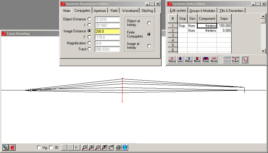
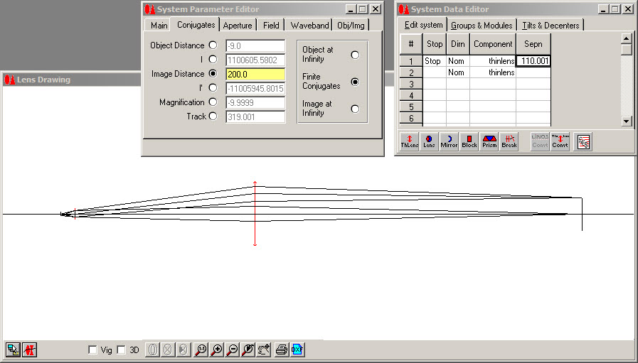
But that's not correct, and here's one illustration, giving 10X magnification at an image distance of 100 mm from the rear lens:

Image

Oddly enough, if the subject then moves closer to the front lens so as to push the image plane back to 200 mm, the magnification still ends up being 10X despite doubling the rear extension!

Image

This latter observation makes complete sense if you think of arriving at these odd configurations by starting with the traditional case of putting a 100 mm tube lens shortly behind a 10 mm infinity objective, and then gradually increasing first the center extension, and then the rear extension.

Starting with the traditional case, increasing the center extension has no effect on magnification because that region is focused at infinity. You may get vignetting, but none of the ray angles will change. That takes us from the traditional case to the long center section but still 100 mm of "rear extension" from the second lens to the image.

Then to make the second step, increasing the rear extension, we note that the magnification should change as
added_magnification = added_extension / total_f
But because total_f is infinity, added_magnification will be zero and the system will remain fixed at 10X.

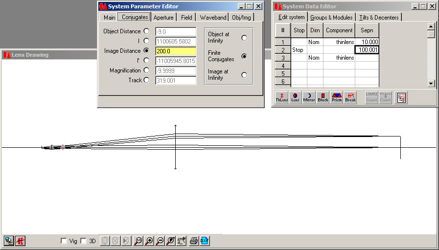
The system becomes even more confusing if you place the limiting aperture between the two lenses, at their common "focus" point 10 mm behind the 10 mm lens and 100 mm in front of the 100 mm lens. In that case the system also becomes telecentric on both sides, as well as fixed magnification!

Here is the ray diagram for 200 mm rear extension in that case.

Image

I'll make another plug here for WinLens3D, a ray-tracing package whose "Basic" version is both free and pretty simple to use. While the math formulations are great for calculation, the ray traces are what give me insight and keep me from misinterpreting or misapplying the formulas.

WinLens3D does have a few limitations, one of which is that it can't handle exactly the system we've been talking about! When I specify e = f1+f2 exactly, with finite conjugates, WinLens3D complains that "Err: 6 Overflow // SysDatEventDirect // Suggest you reverse last action if possible". Then the trick becomes to perturb the optics just far enough to avoid overflow in the arithmetic, without having any significant effect on the ray traces. Hence, 110.001 mm of separation, versus the exact 110.

Great fun, eh?

--Rik

michael_r
Posts: 30
Joined: Sun Jan 22, 2012 5:46 am
Location: Bavaria

Post by michael_r »

Very interesting Rik - i know the (afocal) case f1+f2=e which is widely employed in two-sided telecentric optics used for measuring purposes (Schneider-Kreuznach e.g. produces a series of such lenses - and has published a nice tutorial on telecentric optics, that might be of interest to others). I obviously have to review my understanding of the f1+f2<e case.

Yes its fun to get new insights!

Kind regards

Michael

ploum
Posts: 256
Joined: Sat Oct 18, 2014 6:35 am
Location: France

Post by ploum »

Happy to see this discussion about my system :). My system is fast too. Great !

I take 300 photo in 5 minutes.
I work with a manfrotto 454 but uncommon system :).
Objectives : BW APO PLAN 5x, Mitutoyo APO PLAN 7.5x, 10x, 20x and 50x, Seiwa APO PLAN 20x, BW APO PLAN 20x, Seiwa APO PLAN 10x, Nikon CF PLAN 50x, componon APO 40 mm, Componon 50 mm, Componon S 80 mm, Componon 105 mm, Componon 150 mm, Rodagon 135 mm.....

ploum
Posts: 256
Joined: Sat Oct 18, 2014 6:35 am
Location: France

Post by ploum »

I expose a picture of my system here (sorry for my english !)

To adapt image at the size of the captor i use a raynox DRC 150. In this case, we can see on figure than real image (blue) is less tall than virtual image (green).


this adapation give property of my system : Great optical precision and small size variation.

Image
I work with a manfrotto 454 but uncommon system :).
Objectives : BW APO PLAN 5x, Mitutoyo APO PLAN 7.5x, 10x, 20x and 50x, Seiwa APO PLAN 20x, BW APO PLAN 20x, Seiwa APO PLAN 10x, Nikon CF PLAN 50x, componon APO 40 mm, Componon 50 mm, Componon S 80 mm, Componon 105 mm, Componon 150 mm, Rodagon 135 mm.....

ploum
Posts: 256
Joined: Sat Oct 18, 2014 6:35 am
Location: France

Post by ploum »

Here with a similar case with me (i think)

variation size of image is very small. Pink ray are horizontal, slope could be change if you move L2. An inversion is possible.

Image
I work with a manfrotto 454 but uncommon system :).
Objectives : BW APO PLAN 5x, Mitutoyo APO PLAN 7.5x, 10x, 20x and 50x, Seiwa APO PLAN 20x, BW APO PLAN 20x, Seiwa APO PLAN 10x, Nikon CF PLAN 50x, componon APO 40 mm, Componon 50 mm, Componon S 80 mm, Componon 105 mm, Componon 150 mm, Rodagon 135 mm.....

ploum
Posts: 256
Joined: Sat Oct 18, 2014 6:35 am
Location: France

Post by ploum »

Example of result with this system.


Image

Image
I work with a manfrotto 454 but uncommon system :).
Objectives : BW APO PLAN 5x, Mitutoyo APO PLAN 7.5x, 10x, 20x and 50x, Seiwa APO PLAN 20x, BW APO PLAN 20x, Seiwa APO PLAN 10x, Nikon CF PLAN 50x, componon APO 40 mm, Componon 50 mm, Componon S 80 mm, Componon 105 mm, Componon 150 mm, Rodagon 135 mm.....

michael_r
Posts: 30
Joined: Sun Jan 22, 2012 5:46 am
Location: Bavaria

Post by michael_r »

Hello Frederic,

i like your mineral images very much - they are really beautiful.

I have to admit that i did not understand the first of your sketches, explaining your setup. I think i understand the second case - with a separation e of the two lenses that is smaller than the sum of the two focal lengths (so e < f1+f2).

In my understanding you move lens L2 together with the camera - keeping the distance between L2 and the sensor constant. Is this correct?

Your example with the 20x nikon: at what magnification did you use the raynox in front of the camera (magnification without L1)?

ploum
Posts: 256
Joined: Sat Oct 18, 2014 6:35 am
Location: France

Post by ploum »

Michael it's right.

I use Raynox DR 150 for camera. This lens don't make a magnification (virtual image). A small reduction of magnification. I take all size of image on sensor like that.
I work with a manfrotto 454 but uncommon system :).
Objectives : BW APO PLAN 5x, Mitutoyo APO PLAN 7.5x, 10x, 20x and 50x, Seiwa APO PLAN 20x, BW APO PLAN 20x, Seiwa APO PLAN 10x, Nikon CF PLAN 50x, componon APO 40 mm, Componon 50 mm, Componon S 80 mm, Componon 105 mm, Componon 150 mm, Rodagon 135 mm.....

michael_r
Posts: 30
Joined: Sun Jan 22, 2012 5:46 am
Location: Bavaria

Post by michael_r »

Hello Frederic,

i'm still curious: what is the distance (accurcay +/- 1 cm would be sufficient to me) between Raynox and sensor if you make images with the 20x nikon [i assume together with the "tube lens" (which can be combined with the nikon to L1 in the discussion)]?

ploum
Posts: 256
Joined: Sat Oct 18, 2014 6:35 am
Location: France

Post by ploum »

This distance is ever the same. Last optimisation = 8 cm for my micro 4/3 sensor Panasonic.
I work with a manfrotto 454 but uncommon system :).
Objectives : BW APO PLAN 5x, Mitutoyo APO PLAN 7.5x, 10x, 20x and 50x, Seiwa APO PLAN 20x, BW APO PLAN 20x, Seiwa APO PLAN 10x, Nikon CF PLAN 50x, componon APO 40 mm, Componon 50 mm, Componon S 80 mm, Componon 105 mm, Componon 150 mm, Rodagon 135 mm.....

ploum
Posts: 256
Joined: Sat Oct 18, 2014 6:35 am
Location: France

Post by ploum »

Perhaps in mineralientage this year .... For moment i'm waiting for friday tickets....
I work with a manfrotto 454 but uncommon system :).
Objectives : BW APO PLAN 5x, Mitutoyo APO PLAN 7.5x, 10x, 20x and 50x, Seiwa APO PLAN 20x, BW APO PLAN 20x, Seiwa APO PLAN 10x, Nikon CF PLAN 50x, componon APO 40 mm, Componon 50 mm, Componon S 80 mm, Componon 105 mm, Componon 150 mm, Rodagon 135 mm.....

michael_r
Posts: 30
Joined: Sun Jan 22, 2012 5:46 am
Location: Bavaria

Post by michael_r »

Thank you for the information Frederic - a distance of 8 cm between Raynox and sensor cannot give a real image of the second stage. In my investigation in the original thread (Ploums setup) i assumed that the second stage alone produces a real image. In order to keep up with the new information concerning your setup i made an update of the work presented there. I added it to the original thread as our discussion here somehow begins to deviate from the title of this thread.

Michael

PS: I think about going to the munich show - but on saturday not an friday as i'm only a "tourist visitor".

Post Reply Previous topicNext topic