Anatomy of a liquid CPU cooler

Have questions about the equipment used for macro- or micro- photography? Post those questions in this forum.

Moderators: rjlittlefield, ChrisR, Chris S., Pau

rjlittlefield
Site Admin
Posts: 23601
Joined: Tue Aug 01, 2006 8:34 am
Location: Richland, Washington State, USA
Contact:

Anatomy of a liquid CPU cooler

Post by rjlittlefield »

This is one of my occasional autopsy reports.

A few days ago I noticed that my computer's fans were running fast even though I thought it shouldn't be doing much. I checked for the usual offenders, found a runaway Adobe Reader and Firefox, rebooted, cpu then at zilch but still fast fans. Real Temp (a temperature monitoring program) showed overly high cpu temperature. It occurred to me that it had been a long time since I blew it out, so I popped it apart and did that. Got a satisfying lot of dust, all paths looked clean. Plugged it together, expected the problem to be gone. Nope, worse. Checked airflow on all case fans, seemed great. Opened up the case, reseated fan connections. No change, at best -- actually the problem seemed to be getting rapidly worse. In a short while I could barely complete a boot. Real Temp then showed a very rapid rise to 95C, 0 margin, status HOT, and a very short while later the system would shut down. After some struggling, I got it up just long enough to see in the advanced boot status that indeed the cpu fan claimed to be running.

Bear in mind, this particular machine has a liquid cooler for the CPU. That device is basically the same as a car's radiator and water pump, except much smaller and sold as one integrated unit.

After some discussion with the fellow who built the machine, we decided the quickest and simplest solution was to just buy an exact replacement. They're not terribly expensive, so even with overnight shipping and an extra tube of heat sink paste thrown in just in case, it was less than $100 to get the computer running again.

Then came the question: what to do with the failed unit? This was a Corsair H60, which according to the box has a 5-year warranty. On the other hand, I had already replaced the unit, I didn't need another to keep on the shelf, and my curiosity was highly aroused. What had made the beast fail??? Of course this question provided the answer to my other one about what to do: rip it apart to see what's inside!!

At this point my luck took a turn for the better. It turns out that although the beast is not designed to be maintained, it is designed to come apart. Everything that matters, at least for this discussion, is fastened together with screws.

So, screwdriver in hand, onward!

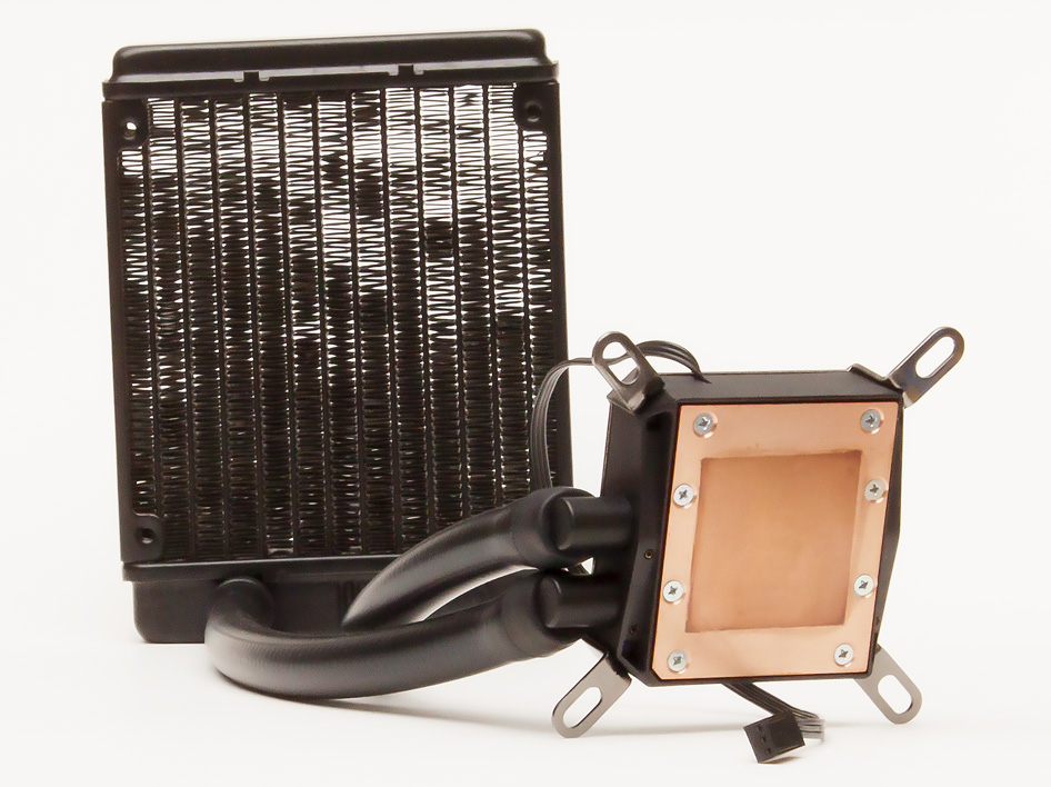
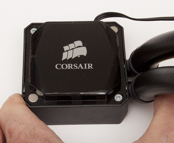
Overview, still fully assembled. (OK, re-assembled, but who's counting?) The radiator web is not at all clogged, by the way. It's just that the vanes are close together and vary a bit in angle, so we can only see between some of them from any one viewpoint. The copper plate with the dark rectangle on it is what presses against the processor chip to keep it cool.

Image

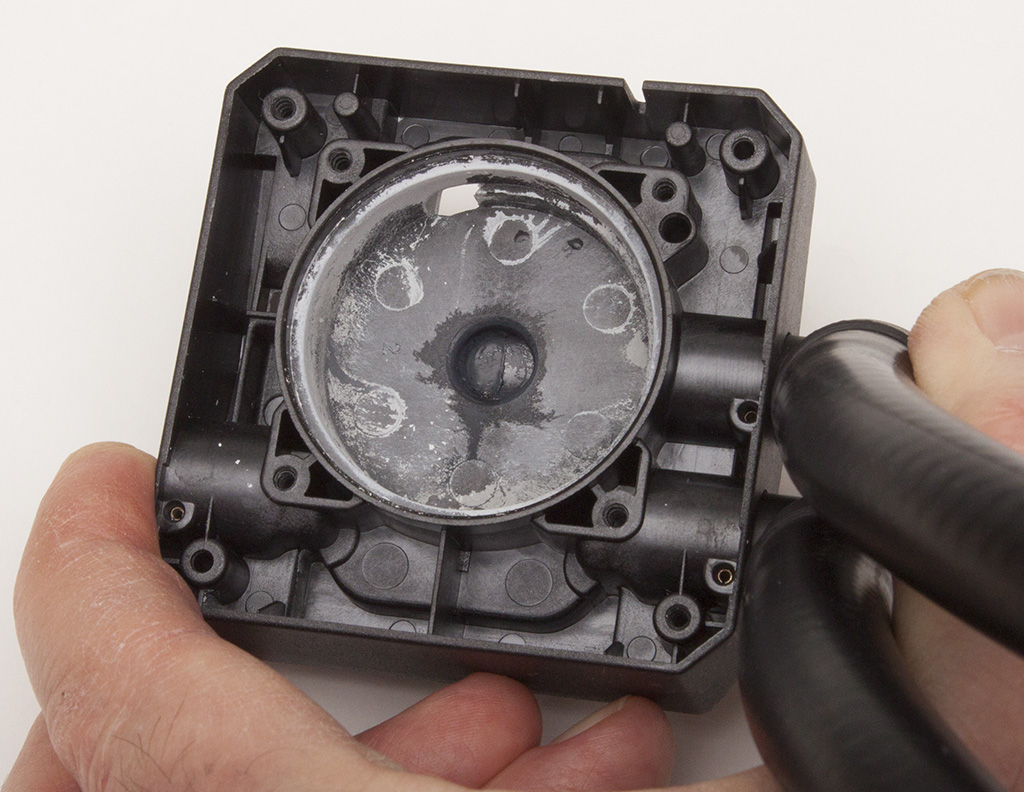
Removing the screws on the copper plate opens the fluid chamber so that all the coolant can run out. (More about that later.) After rinsing things out and letting them dry, this is what we have:

Image

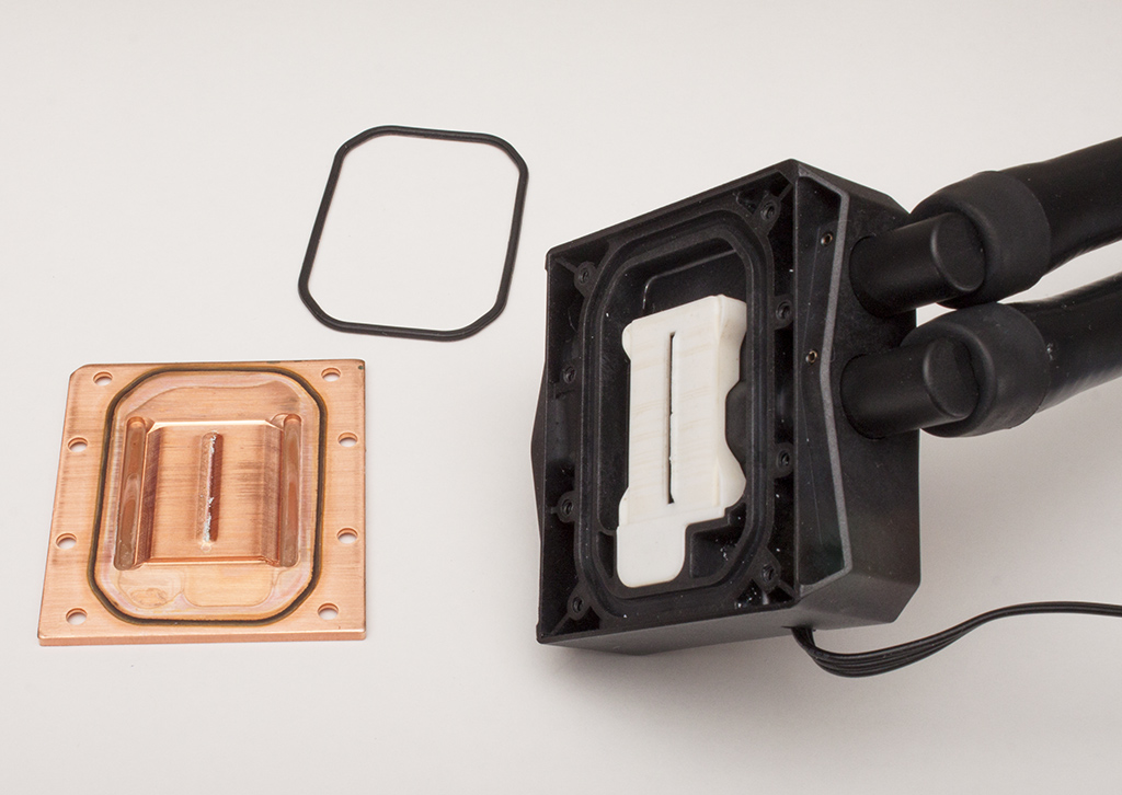
In the above picture, the black octagonal ring and the white lumpy thing are elastomeric seals. In this view, cool fluid gets pumped out the central slit in the white seal, flows from the center of the copper block toward its edges, passing through a set of finely spaced vanes milled into the copper so as to pull heat away from the processor. The hot fluid then exits through the tube near the corner of the black block, runs out through the radiator where it cools down, then comes back through the other tube to resume the cycle.

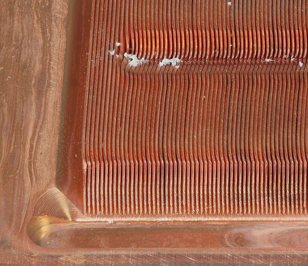
Here is a closeup of the milled vanes in the copper plate. Those white lumps in the central groove? More about that in a minute.

Image

OK, turning the pump block over and disassembling it from the top side, this is what we see...

There's a 4-cornered spring clamp that holds the cooling unit tight against the processor chip.

Image

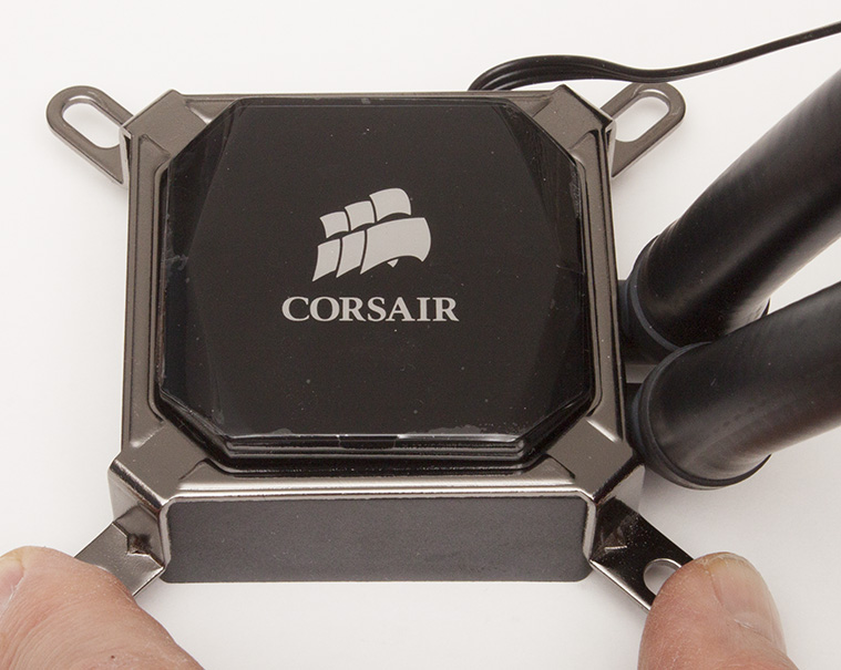
The clamp is just held on by a couple of magnets. It pulls right off to reveal two screws that hold on the pump cover.

Image

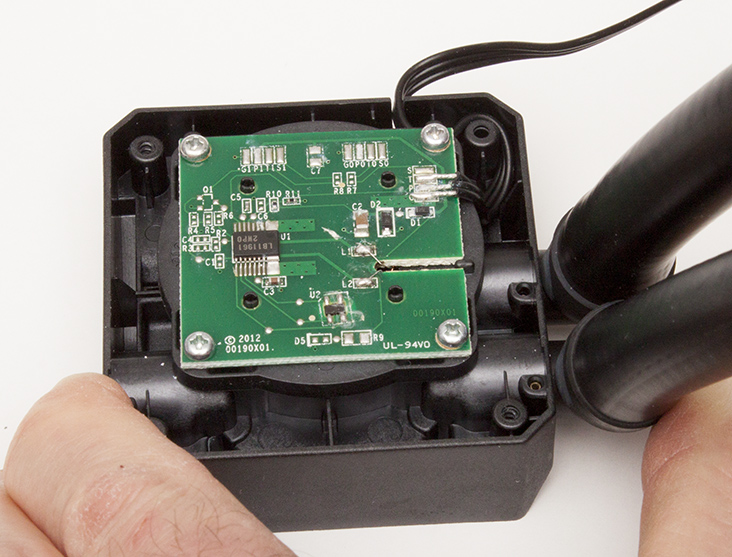
Removing the cover exposes the motor control card. What a surprise -- the main chip is number LB11961, a "Single-Phase Full-Wave Fan Motor Driver".

Image

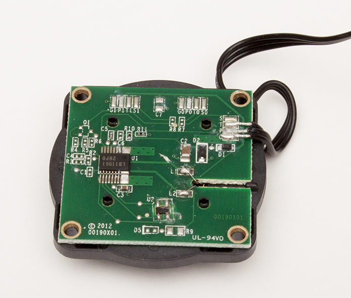
Removing the four screws frees the controller card and a plastic block on which the motor is mounted.

Image

Removing that, and turning it over, reveals the impeller of a centrifugal pump.

Image

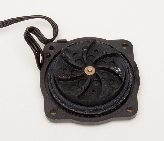
Meanwhile the pump housing now shows the route for coolant being pumped: feed into the center of the impeller and out the hole seen at top center of the photograph.

Image

I powered up the pump and found that it still works fine.

So what was the failure??

Well, you probably remember that coolant I mentioned, the stuff that ran out as soon as I unscrewed the copper plate. The stuff looked very familiar, visually identical to what I put in my car, except for one small detail.

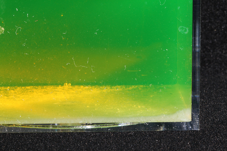
Here's what the stuff from the cpu cooler looks like, after it's had a chance to settle in its storage container. Ignore the lint on the outside of the container, but do notice the white layer on the bottom.

Image

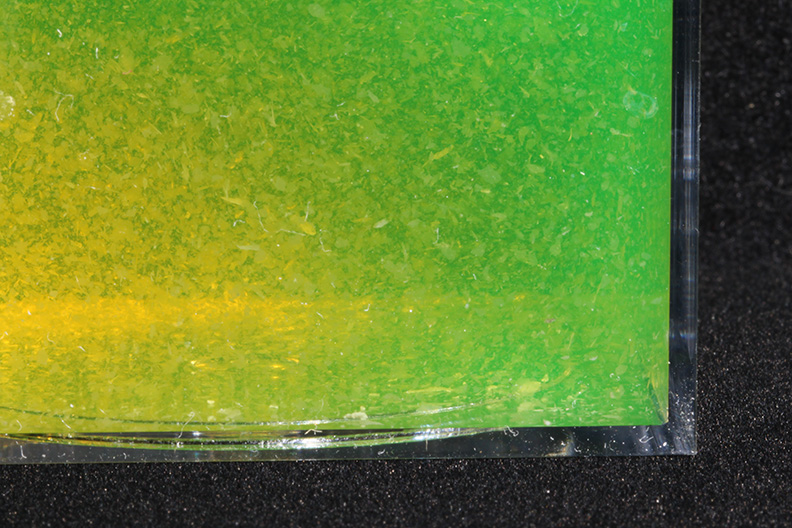
Here's what it looks like when agitated:

Image

So now I'm about 99% sure that the failure was simple: the entrances to the fine cooling vanes on the copper plate just got blocked off by a nasty thick deposit of those flakes. You can see some remains of them, now dried into lumps that look a bit like salt, still sitting in the central groove of the copper plate. I'll bet that in operation (OK, non-operation), the groove was completely filled with that junk. No coolant flow, no heat transfer, no computing.

There are some high magnification images and related discussion of the coolant flakes over in the microscope forum, Circulating debris in a liquid CPU cooler, crystal mats. At first I had thought they were some sort of biofilm, based mostly on what looked like gelatinous goo when collected en masse on the wet cooling fins. But closer examination and a few simple experiments reveals that the flakes are actually collections of long very thin crystals, grown into a sort of interlocking mat that is surprisingly robust.

The cooler may develop a second life, by the way. I'm toying with the idea of using it as part of a Peltier cooled stage, to pull heat off the hot side of the Peltier module. It turns out that I can't use the built-in motor for that job, because it vibrates too much. On the other hand there seems to be no reason why I can't force fluid through the system with an external pump that would be vibration isolated from the heat exchange module. It's an idea for later, anyway.

I hope you find this interesting!

--Rik

pontop
Posts: 83
Joined: Wed Dec 18, 2013 4:00 am
Location: Uppsala, Sweden

Post by pontop »

Interesting indeed. And immediately brings up the question: What do you plan to photograph that needs a peltier cooled stage? Snowflakes?

/Bo

MaxRockbin
Posts: 188
Joined: Sat Nov 08, 2014 11:12 pm
Location: Portland, OR

Post by MaxRockbin »

That's really interesting. I always assumed these liquid coolers were simpler.

For one thing, why do you think they chose to make the pump integrated with the cooler block itself instead of having it completely disconnected and just attached to the in or out hose? I thought that was how they worked. Maybe just because it's easier to fit in a computer case?

Maybe you could rig an external pump up that way for your peltier repurposing?
If your pictures aren't good enough, you're not close enough. - Robert Capa

g4lab
Posts: 1437
Joined: Fri May 23, 2008 11:07 am

Post by g4lab »

Very interesting. I just happened to look at an advert for one of those things and wondered (until I saw multiple motor leads) whether they were active or passive like some of the more primitive ones.

rjlittlefield
Site Admin
Posts: 23601
Joined: Tue Aug 01, 2006 8:34 am
Location: Richland, Washington State, USA
Contact:

Post by rjlittlefield »

pontop wrote:What do you plan to photograph that needs a peltier cooled stage? Snowflakes?
I'm more thinking of a place to keep insects chilled. They often calm down pretty nice in the refrigerator, but then warm up too fast to photograph.
MaxRockbin wrote:For one thing, why do you think they chose to make the pump integrated with the cooler block itself instead of having it completely disconnected and just attached to the in or out hose?
I assume it's a combination of manufacturing cost and convenience for the user. The way they have it done here, the pump block clamps to the processor and the radiator screws to a case fan. If they had a pump that was separated from the cpu block, then they'd have another block to make, and no obvious place to mount it.

Yes, for peltier repurposing, I would plan to use an external pump. To avoid vibration at the copper block unit, it might be necessary to do something to keep the impeller from turning under influence by the fluid getting forced through.
g4lab wrote:wondered ... whether they were active or passive like some of the more primitive ones.
This is the only one I've seen. Kept busy by Prime95, my cpu reports consuming 89 watts. (Oddly, that's with "Small FFTs maximum FPU stress", not "In-place large FFTs maximum heat.") I have trouble imagining transferring that much power with passive liquid flow in the small space these things have to use. Maybe a heat-pipe design using phase-change refrigerant?

--Rik

Edit: typo, "pace" --> "place"
Last edited by rjlittlefield on Fri Feb 27, 2015 9:16 pm, edited 1 time in total.

ChrisR
Site Admin
Posts: 8671
Joined: Sat Mar 14, 2009 3:58 am
Location: Near London, UK

Post by ChrisR »

phase-change refrigerant?
It did occur to me - though I discounted it as unlikely, that the crystals you're seeing were exactly that. Do they dissappear readily on heating? If the chemistry were slightly wrong, could they simply be too big, so they cause a blockage?

(The pillars supporting the Alaskan oil pipeline have circulating phase-change coolant to stop the ground warming too much. Utterly irrelevant here, but neat!)

rjlittlefield
Site Admin
Posts: 23601
Joined: Tue Aug 01, 2006 8:34 am
Location: Richland, Washington State, USA
Contact:

Post by rjlittlefield »

ChrisR wrote:Do they dissappear readily on heating?
No. Soaking a vial of the crystals+coolant in a boiling-water bath for 15 minutes produced no visible effect.

--Rik

MaxRockbin
Posts: 188
Joined: Sat Nov 08, 2014 11:12 pm
Location: Portland, OR

Post by MaxRockbin »

I think the same liquid is used for thermal transfer in solar water heating systems (dilute propylene glycol). So it's supposed to handle very cold and very warm temps without clogging things up. They don't use anti-freeze Just In Case somehow the fluid got into the water supply. Propylene G. is non-toxic. I just googled and you can get a gallon for $20 intended to prevent Ketosis in cows.

It really seems like something got in there and contaminated the works causing the crystals to form. Too many systems depend on PEG for this to be a normal thing.

I wonder if you could substitute mercury...
It would transfer heat a lot better. Though, apparently it expands a fair bit with temperature or thermometers wouldn't work. I don't know if normal pumps would like it. Heavy. But people use it:
A heat transfer medium (such as mercury) fills each of the heat pipes.
http://www.google.com/patents/US4560533
If your pictures aren't good enough, you're not close enough. - Robert Capa

g4lab
Posts: 1437
Joined: Fri May 23, 2008 11:07 am

Post by g4lab »

The heat pipe ones do use some kind of phase change refrigerant. I think some kind of freon related compound. I have a couple of them around here that I could not bear to pitch when I scrapped some relatively recent dead computers. Some have copper heat transfer tubes. Others, the whole thing looks nickel or matt chrome plated.

lothman
Posts: 966
Joined: Sat Feb 14, 2009 7:00 am
Location: Stuttgart/Germany

cooling stage

Post by lothman »

rjlittlefield wrote:
Fri Feb 27, 2015 3:41 pm

I'm more thinking of a place to keep insects chilled. They often calm down pretty nice in the refrigerator, but then warm up too fast to photograph.

Hi Rik,
I just have to dig this out. Since I have a new macro rig (around a thorlabs 66mm rail) with high stability and room for a cooling stage, I am thinking of a source for cooling. Did this CPU liquid cooler work? Any problems with vibrations due to the pump directly mounted on the cooler?

regards
Lothar

Bakwetu
Posts: 42
Joined: Mon Feb 10, 2020 6:32 pm

Re: Anatomy of a liquid CPU cooler

Post by Bakwetu »

Usually when there is goo like that in the water cooling system it is due to plasticizers in the tubes that leaks. The plasticizers is what makes the tubes soft and bendy, but since this is a problem that has been known for some years there are tubes that are supposedly not leaking anything out in the water. https://www.overclock.net/forum/61-wate ... cizer.html

chris_ma
Posts: 571
Joined: Fri Mar 22, 2019 2:23 pm
Location: Germany

Re: cooling stage

Post by chris_ma »

lothman wrote:
Sun Jun 28, 2020 3:25 am
I just have to dig this out. Since I have a new macro rig (around a thorlabs 66mm rail) with high stability and room for a cooling stage, I am thinking of a source for cooling. Did this CPU liquid cooler work? Any problems with vibrations due to the pump directly mounted on the cooler?
Hi,

the liquid cooler itself can't cool at all, it's just a thermal transport system. usually it transports heat from a very hot CPU to relatively cool air.

for cooling below ambient temperature, you need either a cold reservoir (a bucket of ice) or a heat pump.
what Rik was describing is using a peltier element as heat pump, and the liquid cooling system to make it more efficient to transport the heat off the hot side of the peltier.

I've never attempted anything like that, but for short sessions it might be easier to just use some ice cube to chill the air around it.
chris

Adalbert
Posts: 2456
Joined: Mon Nov 30, 2015 1:09 pm

Re: Anatomy of a liquid CPU cooler

Post by Adalbert »

Hello Rik,
Very interesting and so exciting!
BTW, I have installed the “Corsair Hydro Series iCUE H115i RGB Pro XT” in my computer :-(
BR, ADi

rjlittlefield
Site Admin
Posts: 23601
Joined: Tue Aug 01, 2006 8:34 am
Location: Richland, Washington State, USA
Contact:

Re: Anatomy of a liquid CPU cooler

Post by rjlittlefield »

Bakwetu wrote:
Sun Jun 28, 2020 6:35 am
Usually when there is goo like that in the water cooling system it is due to plasticizers in the tubes that leaks.
I have no idea about the frequency of one cause versus another. But in this case the "goo" was clearly a collection of small needle-shaped crystals that retain their shape when dried, as discussed in more detail at viewtopic.php?t=26633 . It's not the sort of structural form that I'd expect from aggregated plasticizer.
chris_ma wrote:
Sun Jun 28, 2020 9:49 am
what Rik was describing is using a peltier element as heat pump, and the liquid cooling system to make it more efficient to transport the heat off the hot side of the peltier.
Correct. And I never got around to pursuing the idea. At this moment I'm not sure whether I even still have the failed cooler. I might have thrown it out to make space for other "stuff".

--Rik

pierre
Posts: 289
Joined: Mon Jan 04, 2010 12:37 pm
Location: France, Var, Toulon

Re: Anatomy of a liquid CPU cooler

Post by pierre »

Impressive results.
Many thanks sharing your experience & analyze Rik !
Regards

Pierre

Post Reply Previous topicNext topic