* This post is more of a "Note to self"....
This thread has jogged my memory (it constantly needs jogging). In this case, I was reminded of the "Frozen Humming Birds" entry at www.strobist.com blog.
The link below is a brief discussion (with additional links) that may be helpful/relevant when discussing the importance of flash output duration and diffusion.
It basically deals with the importance of retaining (as much as possible) the flash duration/output range, so that the option is available if/when you find it necesary to use your flash duration as your shutter speed or "virtual shutter"; hence, the important distinction of diffusing rather than blocking the light; a key aspect (one of many) given due consideration in morfa's design.
http://www.photomacrography.net/forum/v ... php?t=7195
Craig
A Macro Beauty-dish Diffuser
Moderators: rjlittlefield, ChrisR, Chris S., Pau
-
augusthouse

- Posts: 1195
- Joined: Sat Sep 16, 2006 1:39 am
- Location: New South Wales Australia
-
augusthouse
- Posts: 1195
- Joined: Sat Sep 16, 2006 1:39 am
- Location: New South Wales Australia
I have attempted to create a similar 'diffuser' to morfa's.
It has been built to house a Canon 580 EX II (a big flash unit).
Some pictures below to provide an indication of the components and where I am at with it at the moment.
The container I have used for this prototype is not quite elliptical, so will need to find a more appropriate solution for more reasons than one.
The container in the images is 8cm deep, 13cm wide at the front end, 11 cm at rear end and 11cm high with the lid/diffuser panel attached.
I initially created a small "V" shape center-weight/partial reflector similar to John's from a thin piece of aluminium; but had difficulty positioning and securing it; so thought I would try something different whilst still hopefully achieving the same performance as in John's design.
The first image shows a $2 flash dome diffuser (similar to eBay #: 170400024303). I have covered the front of this part with RoscoScrim (mesh with black on one side and silver reflector on the other side); specs indicate 25% transmission; but it doesn't seem to be fulfilling the desired center-weight function.....which explains the unmeshed diffuser dome in the second series of images.
Does it work??? Yes and No and Yes (that's the best way I can describe it at this stage)
The plastic dome diffuser attaches to the flash unit with good breathing space between the front of the flash unit and the front of the dome diffuser (the flash unit stops at the halfway mark where that small 'bump' is in the first images.
The almost elliptical diffuser has a rear flange made of foamcore which accommodates the small dome diffuser nicely. Approximately half of the small dome diffuser (15mm) protrudes into the almost ellipitcal, larger diffuser.
I will have more to report as I play 'round with it; but thought I would upload these initial images for your viewing pleasure
Please feel free to jump in with any suggestions or questions while I attempt to list the problems I am having and possible solutions.


Craig
It has been built to house a Canon 580 EX II (a big flash unit).
Some pictures below to provide an indication of the components and where I am at with it at the moment.
The container I have used for this prototype is not quite elliptical, so will need to find a more appropriate solution for more reasons than one.
The container in the images is 8cm deep, 13cm wide at the front end, 11 cm at rear end and 11cm high with the lid/diffuser panel attached.
I initially created a small "V" shape center-weight/partial reflector similar to John's from a thin piece of aluminium; but had difficulty positioning and securing it; so thought I would try something different whilst still hopefully achieving the same performance as in John's design.
The first image shows a $2 flash dome diffuser (similar to eBay #: 170400024303). I have covered the front of this part with RoscoScrim (mesh with black on one side and silver reflector on the other side); specs indicate 25% transmission; but it doesn't seem to be fulfilling the desired center-weight function.....which explains the unmeshed diffuser dome in the second series of images.
Does it work??? Yes and No and Yes
The plastic dome diffuser attaches to the flash unit with good breathing space between the front of the flash unit and the front of the dome diffuser (the flash unit stops at the halfway mark where that small 'bump' is in the first images.
The almost elliptical diffuser has a rear flange made of foamcore which accommodates the small dome diffuser nicely. Approximately half of the small dome diffuser (15mm) protrudes into the almost ellipitcal, larger diffuser.
I will have more to report as I play 'round with it; but thought I would upload these initial images for your viewing pleasure
Please feel free to jump in with any suggestions or questions while I attempt to list the problems I am having and possible solutions.
Craig
To use a classic quote from 'Antz' - "I almost know exactly what I'm doing!"
Hi Craig,
Have the Canon flash units got the same little put out/down diffusion panel that the Nikon units have? This little panel, when deployed, cover a lens of 14mm and surely spreading the beam to that width should be enough to 'break-up' the beam inside the diffuser and get it bouncing around at all angles before exiting the front diffusion panel?
Bruce
Hi Craig,
Nice to see you're experimenting with this design!
I like the idea of using one of those cheap dome diffusers as a base.
Just by looking at it I get the impression that having a flat rather than v-shaped reflector would cause a LOT of light loss since most of the light is made to bounce straight back into the flash. The thinking behind the "V" is to split the main beam into two and trow them in different directions inside the diffuser.
I definitely think it's worth playing around with different reflector shapes (both the small reflector directly in front of the flash (in my case v-shaped) and the big one (in my case the ice cream box)).
Top left of this diagram shows the diffuser as it looks today from above. The black box is the flash head (pointing upwards in the diagram). The red "V" is the primary reflector, the blue is the secondary reflector and the green line is the thin, highly transmissive diffusion material.
My initial thought was that I would get more output by having a less sharp corner towards the bottom of the icecream box so I modified it as is shown in the top right image. While this did improve the output capacity by a small amount it also decreased the diffusion by creating two fairly bright hotspots at either side of the diffuser. This caused me to go back to the original design with a straight angled second reflector.
However, at some point I'd like to try and modify the primary and secondary reflectors as shown in the bottom left. In the bottom right I've also added a third reflector that might be worth playing around with.
/John

Well, it's worth a try if they are easy to come by! But the problem with these shapes is that the central part of the egg/sphere will just reflect the light back into the flash head. You want the opposite – the central part should reflect the light as much as possible to the sides while the outer parts could reflect the light backwards since that would reflect the light back onto the rear parts of the secondary reflector as opposed to back into the flash head.elf wrote:How about using a sphere or a silver plated egg for the primary reflector ?
So the reason I like the idea of the "inverted" circle is that the portion that is perpendicular to the main flash beam (reflecting the light backwards) is located towards the outer parts of the primary reflector. Here is a very hastily made doodle to illustrate my point:
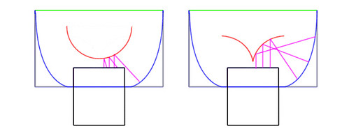
When doodling this I realized that the straight "V" might very well be the best of these options.
/John
-
augusthouse
- Posts: 1195
- Joined: Sat Sep 16, 2006 1:39 am
- Location: New South Wales Australia
I cut a "V" into the face of the small diffuser dome. The 'cut' serves as a cradle for the aluminium "V".
The remaining portion at the front or face of the small dome diffuser may/will also need to be removed (most likely some other bits too)....and then a decision made as to what to use to securely attach the aluminium "V" to the plastic diffuser dome?
The front of the flash unit is located at the ridge in the middle of the small dome diffuser.

Craig
The remaining portion at the front or face of the small dome diffuser may/will also need to be removed (most likely some other bits too)....and then a decision made as to what to use to securely attach the aluminium "V" to the plastic diffuser dome?
The front of the flash unit is located at the ridge in the middle of the small dome diffuser.
Craig
Last edited by augusthouse on Sun Jan 03, 2010 8:36 pm, edited 1 time in total.
To use a classic quote from 'Antz' - "I almost know exactly what I'm doing!"

Yet another possible flash reflector thought
I am concerned that the exit surface of most flash guns is an optical element itself and may confound DIY design efforts.
What if one removed the glass/plastic "lens" that comprises the flash gun's exit surface, and replace it with either a simple diffuser or nothing?
Also, and perhaps using an unmodified flash gun, what about taking a standard flash gun and pointing it backwards (away from the subject) into a mini-umbrella? The umbrella would presumably be a parabolic shape to minimize the number of bounces - each bounce eats a fraction of the light, something that is undesirable. Perhaps the parabola should instead be a parabolic-like shape that would spread the light wider than an accurate parabola? This would be similar to a portrait flash umbrella, but much smaller in size.
Just some late night thoughts - I hope they are of interest or at least entertaining.
-Phil
"Diffraction never sleeps"
"Diffraction never sleeps"
-
augusthouse
- Posts: 1195
- Joined: Sat Sep 16, 2006 1:39 am
- Location: New South Wales Australia
DQE wrote:
Interesting link below; not quite what you are describing (nothing at all like you are describing); but thought it was worth a look as it deals somewhat with the bounce property; not sure how applicable it would be for macro.
http://www.presslite.com/home.php
Craig
Always good to throw ideas aroundJust some late night thoughts - I hope they are of interest or at least entertaining.
Interesting link below; not quite what you are describing (nothing at all like you are describing); but thought it was worth a look as it deals somewhat with the bounce property; not sure how applicable it would be for macro.
http://www.presslite.com/home.php
Craig
To use a classic quote from 'Antz' - "I almost know exactly what I'm doing!"
-
augusthouse
- Posts: 1195
- Joined: Sat Sep 16, 2006 1:39 am
- Location: New South Wales Australia
I've been hacking away at the small diffuser dome (might need to hack some more). It still has a cradle (somewhat smaller but sufficient) for the "V" reflector. Aluminium foil tape should hold it in place nicely. I'm just using plain old sticky tape for the moment.
I have a more suitable elliptical container, still need to line the internals; but after initial observations (insert "V" reflector into elliptal container, attach large diffuser, squint and fire flash) it appears to be providing the desired result.
Craig
I have a more suitable elliptical container, still need to line the internals; but after initial observations (insert "V" reflector into elliptal container, attach large diffuser, squint and fire flash) it appears to be providing the desired result.
Craig
Last edited by augusthouse on Tue Dec 18, 2012 12:03 am, edited 1 time in total.
To use a classic quote from 'Antz' - "I almost know exactly what I'm doing!"
Hi Craig,
It might be worth remembering that fitting the flash diffuser to the flash head automatically triggers the flash to zoom setting of 14/17mm.
At least it does on the Nikon speedlites, and at this setting, I'm unsure as to whether the TTL system will work properly because the flash is unable to zoom to the lens' focal length?
Bruce
-
augusthouse
- Posts: 1195
- Joined: Sat Sep 16, 2006 1:39 am
- Location: New South Wales Australia
Thanks Bruce,
Not a problem with the Canon. It doesn't even know the home-made diffuser is on there; it will when metering, no doubt, but the zoom setting appears unaffected as long as the 'catchlight panel' and/or 'wide angle panel' on the flash unit are not deployed.
I don't have any of the more recent Nikon Speedlights; but do have two SB-28.
Craig
To use a classic quote from 'Antz' - "I almost know exactly what I'm doing!"
Aluminium foil tape should hold it in place nicely. I'm just using plain old sticky tape for the moment.
Hot-melt glue guns are good for this sort of thing. Instant, strong enough, removable...
I've stuck things to Nikon Speedlights without damaging them. Old one was SB24, new one is the current one - too senile to remember new numbers.
TTL flash with that and D700 seems to work whatever I do.
-
Graham Stabler
- Posts: 209
- Joined: Thu Dec 20, 2007 11:22 am
- Location: Swindon, UK
The film Brian has is definitely not light control film as that goes on the front and is to prevent people viewing what you are looking at. The film on the back of the LCD is part of the back lighting, it is used in an effort to create an even lighting. I've been looking at various back lights as a means of creating nice backgrounds to my object movies.
Generally they consist of a thickish perspex piece into the sides of which is coupled the light, either long cold cathodes or more often now strings of LEDs. The back and sides of this are surrounded with white plastic material. The rear face of the perspex is covered in rough dots that have been etched/blasted into the surface, light is constrained within the sheet like a wave guide and then coupled out by the rough areas, it then reflects off the white sheet and goes forwards to the screen through the diffuser sheets that Brian has used. On the screens I have seen there tend to be three sheets, two are rather lens like with fine lines in their surface and one is more like a traditional diffuser.
Even digital photo keychains have neat little back lights somewhat like these.
Graham
-
Graham Stabler
- Posts: 209
- Joined: Thu Dec 20, 2007 11:22 am
- Location: Swindon, UK