I know very well the system that explains Rik. I think his name is AFOCAL, and is the appropriate method for shooting with bird watching telescopes with non-removable lens cameras. I wrote an article about it more than 20 years ago, with the beginning of compact cameras, and most recently, I wrote a blog post to photograph with binoculars and cheap cameras. And I did with my first microfotos that system.
http://pelupolis.blogspot.com.es/2010/0 ... es-de.html
And this is a image taken with my Canon G11 with this metod.
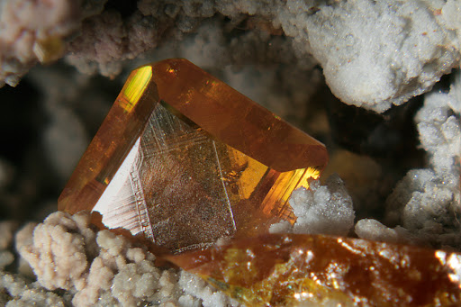
But I found two problems:
First: the exit pupil (the cylinder diameter of rays exiting the lens after Componon) must be bigger than the entrance pupil of the objective lens of camera, and if it is smaller, produces a strong (focused) vignetting, which is the circle of picture I got.
and two: In the scheme of Frederic, he uses a Lumix GF5. Placing the focus point at infinity is the right system, but Frederic places a Raynox front of the lens (at the end, a Raynox is a converging lens) and is impossible to get the compact camera + Raynox focused at infinity. That's why my ray tracing scheme seems so complicated.
Well, I´m learning english and optics. I have luck!

