Yes i agree. But i must see if find something else.
This shows despite everything that it is the whole system whose MTF is measured. Because it is the interpretation of the sensor and its sampling that produces the contrast. After that, it would be necessary to see if the corrections of the contrast in the device can compensate for this fact. Finally, I took into account in my calculations the MTF in a certain way with the 3 pixels for a diffraction spot. So the curves are considering this fact. Indeed we could consider the MTF in addition to the resolution which is modulated by the contrast. Good discussion anyway.
Mitutoyo M Plan APO HR 5X 0.21 Test Results
Moderators: rjlittlefield, ChrisR, Chris S., Pau
Re: Mitutoyo M Plan APO HR 5X 0.21 Test Results
I work with a manfrotto 454 but uncommon system  .
.
Objectives : BW APO PLAN 5x, Mitutoyo APO PLAN 7.5x, 10x, 20x and 50x, Seiwa APO PLAN 20x, BW APO PLAN 20x, Seiwa APO PLAN 10x, Nikon CF PLAN 50x, componon APO 40 mm, Componon 50 mm, Componon S 80 mm, Componon 105 mm, Componon 150 mm, Rodagon 135 mm.....
Objectives : BW APO PLAN 5x, Mitutoyo APO PLAN 7.5x, 10x, 20x and 50x, Seiwa APO PLAN 20x, BW APO PLAN 20x, Seiwa APO PLAN 10x, Nikon CF PLAN 50x, componon APO 40 mm, Componon 50 mm, Componon S 80 mm, Componon 105 mm, Componon 150 mm, Rodagon 135 mm.....
-
rjlittlefield

- Site Admin
- Posts: 23606
- Joined: Tue Aug 01, 2006 8:34 am
- Location: Richland, Washington State, USA
- Contact:
Re: Mitutoyo M Plan APO HR 5X 0.21 Test Results
Yes, we agree on this point.
I think you mean, can digital sharpening compensate for reduced MTF in the optics?it would be necessary to see if the corrections of the contrast in the device can compensate for this fact.
Yes it can, up to a certain point. The issue then is that sharpening always increases noise, so we would then have to consider signal-to-noise issues. Those issues are complicated, and in the end increased noise also affects resolution, by making it more difficult to see low contrast detail. So again, reduced MTF for the objective causes reduced resolution for the overall system. Only the amount of that reduction is difficult to compute.
I do not see this. The curves that I checked, HERE and HERE and HERE, seem to model LP/FOV as just the cutoff frequency of the lens or the sensor, whichever is less. But perhaps I missed something. It is hard to tell because you show only graphs and do not reveal the math behind them.Finally, I took into account in my calculations the MTF in a certain way with the 3 pixels for a diffraction spot. So the curves are considering this fact.
--Rik
Re: Mitutoyo M Plan APO HR 5X 0.21 Test Results
Yes I did not show the math behind. Besides, it would be interesting to see if we can modulate the resolution more subtly by the contrast on the same graph? To calculate the resolutions, I took a low constrate between 2.5 pixels and 3 pixels for a pair of lines. Below I no longer see the contrasts between the lines on a resolution test chart. It would be interesting to see with detailed studies the influence of the MTF and therefore the influence of the number of pixels for a pair of bands on the quality of the images. Then the manufacturers are different and the noise management is different depending on the case. If we could compare two devices with the same sensor but with different noise management ... This is precisely the case with the 61 Mpix. Will the sensor mounted on the sony do a very different job if I increase the digital contrast over the sigma FP L ....? Tests show that the sigma has no noise. It has a low pass filter for that.rjlittlefield wrote: ↑Mon Nov 08, 2021 1:32 am[ But perhaps I missed something. It is hard to tell because you show only graphs and do not reveal the math behind them.
--Rik
I work with a manfrotto 454 but uncommon system .
Objectives : BW APO PLAN 5x, Mitutoyo APO PLAN 7.5x, 10x, 20x and 50x, Seiwa APO PLAN 20x, BW APO PLAN 20x, Seiwa APO PLAN 10x, Nikon CF PLAN 50x, componon APO 40 mm, Componon 50 mm, Componon S 80 mm, Componon 105 mm, Componon 150 mm, Rodagon 135 mm.....
Objectives : BW APO PLAN 5x, Mitutoyo APO PLAN 7.5x, 10x, 20x and 50x, Seiwa APO PLAN 20x, BW APO PLAN 20x, Seiwa APO PLAN 10x, Nikon CF PLAN 50x, componon APO 40 mm, Componon 50 mm, Componon S 80 mm, Componon 105 mm, Componon 150 mm, Rodagon 135 mm.....
Re: Mitutoyo M Plan APO HR 5X 0.21 Test Results
For a FF 24 MPIX. I think about it a bit (I'll take a bit more time as soon as possible). Initially I was ok for your calculations but I am no longer ok at all. I have to clear it all up ... I have improved my spreadsheets but I still have to complete my thoughts.
for the 5x 0.14 sensor MTF is indeed 0.34 but a zero objective MTF. You modulate an MTF of the sensor by a zero MTF of the objective.
Then for the 5x 0.21 the MTF is not the one calculated. Indeed the resolution of the sensor this time is zero. We have 1.2 pixels for a pair of lines. The resolution collapses and gets stuck at a lower value ... I'll analyze all of this. I had taken this into account on my curves by minimum pixel values for a pair of bands. Because without resolution there can be no MTF ... The MTF is therefore calculated with a minimum threshold of perception of the sensor.
This is interesting and I will analyze this.
I work with a manfrotto 454 but uncommon system .
Objectives : BW APO PLAN 5x, Mitutoyo APO PLAN 7.5x, 10x, 20x and 50x, Seiwa APO PLAN 20x, BW APO PLAN 20x, Seiwa APO PLAN 10x, Nikon CF PLAN 50x, componon APO 40 mm, Componon 50 mm, Componon S 80 mm, Componon 105 mm, Componon 150 mm, Rodagon 135 mm.....
Objectives : BW APO PLAN 5x, Mitutoyo APO PLAN 7.5x, 10x, 20x and 50x, Seiwa APO PLAN 20x, BW APO PLAN 20x, Seiwa APO PLAN 10x, Nikon CF PLAN 50x, componon APO 40 mm, Componon 50 mm, Componon S 80 mm, Componon 105 mm, Componon 150 mm, Rodagon 135 mm.....
-
rjlittlefield
- Site Admin
- Posts: 23606
- Joined: Tue Aug 01, 2006 8:34 am
- Location: Richland, Washington State, USA
- Contact:
Re: Mitutoyo M Plan APO HR 5X 0.21 Test Results
Thank you for the update. I am in no hurry. The main thing is to reach agreement about how to do the calculation.ploum wrote: ↑Mon Nov 08, 2021 2:57 pmFor a FF 24 MPIX. I think about it a bit (I'll take a bit more time as soon as possible). Initially I was ok for your calculations but I am no longer ok at all. I have to clear it all up ... I have improved my spreadsheets but I still have to complete my thoughts.
I suggest to look more closely at your calculations. The case that I computed for is 3 pixels per cycle (3 pixels per line pair) on the sensor. On FF 24 MPix, that is 0.018 mm/cycle. On the subject, it is 0.018/5 = 0.0036 mm per cycle = 278 line pairs per mm. That is easily resolvable by NA 0.14, with calculated MTF 34.1%. Neither the sensor nor the objective has zero MTF.for the 5x 0.14 sensor MTF is indeed 0.34 but a zero objective MTF. You modulate an MTF of the sensor by a zero MTF of the objective.
I have no idea where your "1.2 pixels" came from. Again, I calculated for 3 pixels per line pair on sensor, same for both NA 0.14 and 0.21.Then for the 5x 0.21 the MTF is not the one calculated. Indeed the resolution of the sensor this time is zero. We have 1.2 pixels for a pair of lines.
I agree with this approach. That is why I used 3 pixels per line pair in my first comparison, showing 1.6 times more contrast at same resolution.Because without resolution there can be no MTF ... The MTF is therefore calculated with a minimum threshold of perception of the sensor.
In my second comparison, looking at MTF 50 for NA 0.14 versus NA 0.21, you were correct to complain that I did not include sensor MTF in the calculation. In that case sensor MTF will be less for the finer pattern that is resolved by the NA 0.21 objective.
However, including sensor MTF is not difficult if we assume that each pixel has a perfect box function for sensitivity (value 1 inside the pixel, value 0 outside it). In this case the MTF function for sensor sensitivity is sinc(), with frequency scaled so that 1 cycle per pixel gives MTF=0. Incorporating this sensor MTF, 5X NA 0.14 gives 50% system MTF at 4.48 pixels per cycle (where sensor MTF = 0.919 and objective MTF = 0.544), while 5X NA 0.21 gives 50% system MTF at 3.29 pixels per cycle (sensor MTF = 0.855, objective MTF = 0.585). So the ratio of frequencies at 50% system MTF is then 4.48 / 3.29 = 1.36 times higher resolution for NA 0.21.
My earlier calculation that ignored sensor MTF gave a ratio of 1.5 for this comparison, so this is a good illustration that sensor MTF does matter. But in this case it does not matter much, and the 5X NA 0.21 retains a significant advantage over 5X NA 0.14 .
--Rik
Re: Mitutoyo M Plan APO HR 5X 0.21 Test Results
At first I had a doubt with what you were saying Rick. But I have no more doubts. I am sure of my thinking at the moment. You calculate a partial MTF or you have to calculate an MTF for the objective and for the sensor. My curves do this with a minimum criterion of 2.5 pixels for a pair of lines. The global MTF varies, it is true and I will therefore put an MTF criterion on my curves. An example when you take the 5x 0.14 objective. The cutoff frequency is 500 LP / mm (zero MTF) for the lens. On the sensor the MTF of the sensor is 96 LP / mm for a frequency of 166 LP / mm (pixel is 6 um). So you have a bad MTF. However, the whole gives a zero MTF. You will see a signal on the sensor but from an invisible target. The signal frequency does not pass through the object even though the sensor could partially see. For the case of 5x 0.21, the problem is different. It is rather the reverse (as I pointed out between the oversampling of the sensor and the diffraction part of the objective). In this case the cut-off frequency of the objective is 770 LP / mm and the frequency on the sensor is then 150 LP / mm for a cut-off frequency of 166 LP / mm ... Your sensor has zero MTF. He cannot see what the objective gives. I put in my curves a criterion of 2.5 pixels for a pair of tapes because this is what I observe in reality so that the sensor analyzes what could pass through the lens. It is therefore necessary to go back to the corresponding frequency (taking into account the magnification factor) to see if it passes through the objective. I will put an overall MTF on my curves with specific criteria.
I work with a manfrotto 454 but uncommon system .
Objectives : BW APO PLAN 5x, Mitutoyo APO PLAN 7.5x, 10x, 20x and 50x, Seiwa APO PLAN 20x, BW APO PLAN 20x, Seiwa APO PLAN 10x, Nikon CF PLAN 50x, componon APO 40 mm, Componon 50 mm, Componon S 80 mm, Componon 105 mm, Componon 150 mm, Rodagon 135 mm.....
Objectives : BW APO PLAN 5x, Mitutoyo APO PLAN 7.5x, 10x, 20x and 50x, Seiwa APO PLAN 20x, BW APO PLAN 20x, Seiwa APO PLAN 10x, Nikon CF PLAN 50x, componon APO 40 mm, Componon 50 mm, Componon S 80 mm, Componon 105 mm, Componon 150 mm, Rodagon 135 mm.....
Re: Mitutoyo M Plan APO HR 5X 0.21 Test Results
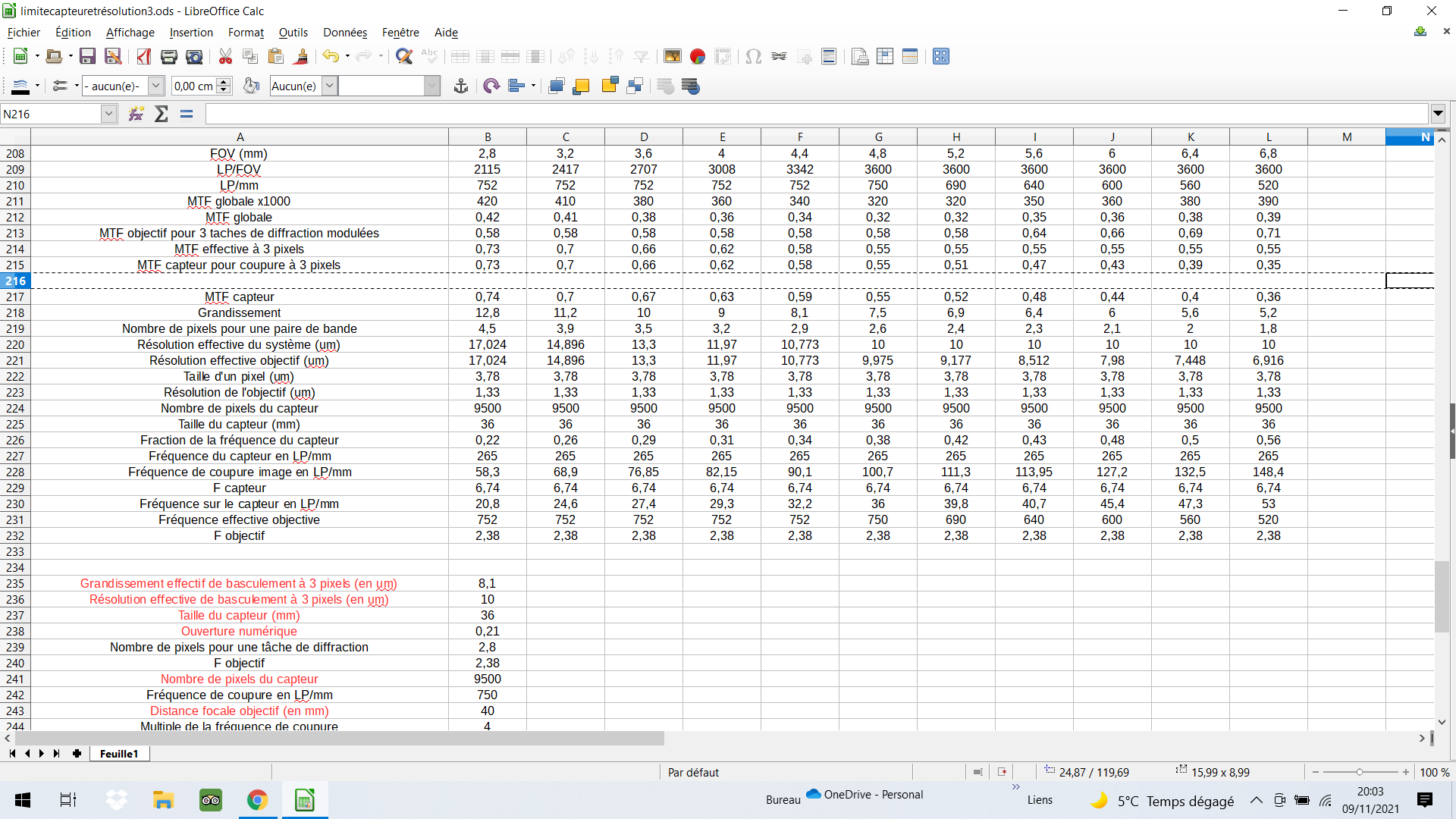
The problem was a bit complex. But I have finished functional sheets. This ultimately does not change my initial curves, but I can put an MTF with it. Indeed the MTF of the sensor normally tends to decrease when FOV increase. When the sensor reaches its limits for sampling then the effective frequency of the objective decreases. This then causes an increase in the constrate of the objective while that of the sensor no longer varies.
https://www.geoforum.fr/uploads/monthly ... 8cc5dd.png
https://www.geoforum.fr/uploads/monthly ... 8cc5dd.png
I work with a manfrotto 454 but uncommon system .
Objectives : BW APO PLAN 5x, Mitutoyo APO PLAN 7.5x, 10x, 20x and 50x, Seiwa APO PLAN 20x, BW APO PLAN 20x, Seiwa APO PLAN 10x, Nikon CF PLAN 50x, componon APO 40 mm, Componon 50 mm, Componon S 80 mm, Componon 105 mm, Componon 150 mm, Rodagon 135 mm.....
Objectives : BW APO PLAN 5x, Mitutoyo APO PLAN 7.5x, 10x, 20x and 50x, Seiwa APO PLAN 20x, BW APO PLAN 20x, Seiwa APO PLAN 10x, Nikon CF PLAN 50x, componon APO 40 mm, Componon 50 mm, Componon S 80 mm, Componon 105 mm, Componon 150 mm, Rodagon 135 mm.....
Re: Mitutoyo M Plan APO HR 5X 0.21 Test Results
So the MTF of my lens does not vary with the FOV as long as the sensor is sampled correctly. In this case the MTF of the sensor decreases when the a FOV increases and the MTF of the assembly decreases. On the other hand, the resolution of the system increases when the FOV increases. When the sensor reaches its sampling limit then the frequency of objects visible to the system decreases. This fact increases the contrast of the objective which is no longer constant. On the other hand, the resolution of the system decreases due to the limitation of the sensor.
Look this example
That's was very interessant. Thanks for this discussion.
https://www.geoforum.fr/uploads/monthly ... 0a5a5c.png
Look this example
That's was very interessant. Thanks for this discussion.
https://www.geoforum.fr/uploads/monthly ... 0a5a5c.png
I work with a manfrotto 454 but uncommon system .
Objectives : BW APO PLAN 5x, Mitutoyo APO PLAN 7.5x, 10x, 20x and 50x, Seiwa APO PLAN 20x, BW APO PLAN 20x, Seiwa APO PLAN 10x, Nikon CF PLAN 50x, componon APO 40 mm, Componon 50 mm, Componon S 80 mm, Componon 105 mm, Componon 150 mm, Rodagon 135 mm.....
Objectives : BW APO PLAN 5x, Mitutoyo APO PLAN 7.5x, 10x, 20x and 50x, Seiwa APO PLAN 20x, BW APO PLAN 20x, Seiwa APO PLAN 10x, Nikon CF PLAN 50x, componon APO 40 mm, Componon 50 mm, Componon S 80 mm, Componon 105 mm, Componon 150 mm, Rodagon 135 mm.....
Re: Mitutoyo M Plan APO HR 5X 0.21 Test Results
I can't quite follow these calculations, but it seems to me that there's some things missing..
for example, I don't see any mention of the tube lens here, but this will affect the total system MTF as well (as will cover glass thickness and debayer algorithm, and object structure - for example slanted lines might show different MTF then horizontal/vertical lines).
so in the end, while the theory is useful for making certain predictions, in the end real world tests (if done properly) still seem more accurate in general.
chris
Re: Mitutoyo M Plan APO HR 5X 0.21 Test Results
These calculations are for a perfect optical system. Of course we could add calculations. The interest is to verify the theory by practice. I have already checked my resolution curves in practice ....
The experience is useful but the interpretation of the experience can only be done correctly if we know where we are going ...
The experience is useful but the interpretation of the experience can only be done correctly if we know where we are going ...
I work with a manfrotto 454 but uncommon system .
Objectives : BW APO PLAN 5x, Mitutoyo APO PLAN 7.5x, 10x, 20x and 50x, Seiwa APO PLAN 20x, BW APO PLAN 20x, Seiwa APO PLAN 10x, Nikon CF PLAN 50x, componon APO 40 mm, Componon 50 mm, Componon S 80 mm, Componon 105 mm, Componon 150 mm, Rodagon 135 mm.....
Objectives : BW APO PLAN 5x, Mitutoyo APO PLAN 7.5x, 10x, 20x and 50x, Seiwa APO PLAN 20x, BW APO PLAN 20x, Seiwa APO PLAN 10x, Nikon CF PLAN 50x, componon APO 40 mm, Componon 50 mm, Componon S 80 mm, Componon 105 mm, Componon 150 mm, Rodagon 135 mm.....
-
rjlittlefield
- Site Admin
- Posts: 23606
- Joined: Tue Aug 01, 2006 8:34 am
- Location: Richland, Washington State, USA
- Contact:
Re: Mitutoyo M Plan APO HR 5X 0.21 Test Results
I totally agree. The only reason that I'm bothering to calculate at all is because of phrases like "no matter what the theory predicts", as if theory did NOT predict that the NA 0.21 objective would be better. The main message of my MTF calculations is that standard theory says that 5X NA 0.21 should be expected to beat 5X NA 0.14 for visual sharpness, even on low-pixel-count sensors like FF 24 Mpix.
Me either. Of course I can follow my own calculations, though I can't tell whether anybody else does. I'm using the standard approach of comparing two objectives at the same level of detail, at the same magnification, on the same sensor, and the calculations are clear that NA 0.21 gives significantly higher contrast. Ploum is using some other sort of analysis that involves changing the FOV, and I'm still trying to figure out exactly what that analysis is doing.I can't quite follow these calculations
Again, I totally agree. All of these issues are difficult to handle mathematically. For example, while it is often written that MTF's multiply, that actually does not apply for one lens followed by another. As an example, you can have one lens whose MTF would be awful due to undercorrected spherical aberration, followed by another lens whose MTF would be equally awful due to overcorrected spherical aberration, but if the aberrations cancel, then the combined MTF would be great. We already see some hint of interactions like that in Robert's report, in that the same Raynox tube lens gives best results with one objective at minimal spacing, while another objective is best with 50 mm. In other words, Robert found that slightly different tube lens setups were needed to get the best results from each objective.I don't see any mention of the tube lens here, but this will affect the total system MTF as well (as will cover glass thickness and debayer algorithm, and object structure - for example slanted lines might show different MTF then horizontal/vertical lines
--Rik
Edit: fix typo regarding NA, in first paragraph
-
rjlittlefield
- Site Admin
- Posts: 23606
- Joined: Tue Aug 01, 2006 8:34 am
- Location: Richland, Washington State, USA
- Contact:
Re: Mitutoyo M Plan APO HR 5X 0.21 Test Results
I cannot see this image. My browser reports "The file you were looking for could not be found".ploum wrote: ↑Tue Nov 09, 2021 7:33 amThe problem was a bit complex. But I have finished functional sheets. This ultimately does not change my initial curves, but I can put an MTF with it. Indeed the MTF of the sensor normally tends to decrease when FOV increase. When the sensor reaches its limits for sampling then the effective frequency of the objective decreases. This then causes an increase in the constrate of the objective while that of the sensor no longer varies.
https://www.geoforum.fr/uploads/monthly ... 8cc5dd.png
--Rik
-
rjlittlefield
- Site Admin
- Posts: 23606
- Joined: Tue Aug 01, 2006 8:34 am
- Location: Richland, Washington State, USA
- Contact:
Re: Mitutoyo M Plan APO HR 5X 0.21 Test Results
I see this graph, but I do not see the calculations that produced it. If you want me to understand your work, then I need to see what math you are using.ploum wrote: ↑Tue Nov 09, 2021 7:50 amSo the MTF of my lens does not vary with the FOV as long as the sensor is sampled correctly. In this case the MTF of the sensor decreases when the a FOV increases and the MTF of the assembly decreases. On the other hand, the resolution of the system increases when the FOV increases. When the sensor reaches its sampling limit then the frequency of objects visible to the system decreases. This fact increases the contrast of the objective which is no longer constant. On the other hand, the resolution of the system decreases due to the limitation of the sensor.
Look this example
That's was very interessant. Thanks for this discussion.
https://www.geoforum.fr/uploads/monthly ... 0a5a5c.png
--Rik
Re: Mitutoyo M Plan APO HR 5X 0.21 Test Results
Usual math. Rayleygh criterion, sampling on the sensor, MTF, minimum sampling of the sensor at 2.5-3 pixels per LP ....
https://www.geoforum.fr/uploads/monthly ... d23862.png
https://www.geoforum.fr/uploads/monthly ... d23862.png
I work with a manfrotto 454 but uncommon system .
Objectives : BW APO PLAN 5x, Mitutoyo APO PLAN 7.5x, 10x, 20x and 50x, Seiwa APO PLAN 20x, BW APO PLAN 20x, Seiwa APO PLAN 10x, Nikon CF PLAN 50x, componon APO 40 mm, Componon 50 mm, Componon S 80 mm, Componon 105 mm, Componon 150 mm, Rodagon 135 mm.....
Objectives : BW APO PLAN 5x, Mitutoyo APO PLAN 7.5x, 10x, 20x and 50x, Seiwa APO PLAN 20x, BW APO PLAN 20x, Seiwa APO PLAN 10x, Nikon CF PLAN 50x, componon APO 40 mm, Componon 50 mm, Componon S 80 mm, Componon 105 mm, Componon 150 mm, Rodagon 135 mm.....

Re: Mitutoyo M Plan APO HR 5X 0.21 Test Results
Interesting discussion.
I'm not a theory guy, but in my experience my Mitty 7.5/0.21 and Nikon S Fluor 4/0.20 outresolves/outperforms any 0.13, 0.14, 0.15 objective at any magnification on any camera I used them with: MFT (20MP), APS (26MP), FF (47MP), among others.
I don't currently have a Mitty 5X nor FF camera, but for what it's worth, I just did a quick comparison: S Fluor 4/0.20 vs CF N 4/0.13 @4X. Shoot with Pana G9 (20MP MFT sensor, 3.3 µm pixel pitch) in HR to make diference clearer.
Both images have been processed with the exactly same settings and have the same amount of sharpening applied.
300% crops:
CF N 4:
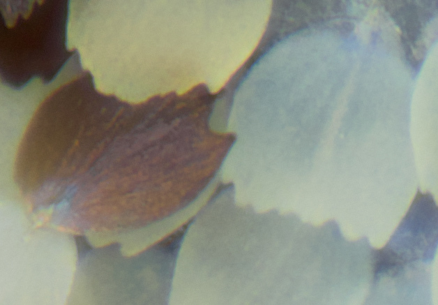
S Fluor 4:

Those scales aren't easy to resolve at 4X, even the 0.20 is struggling, but the 0.13 barely resolves any detail.
So at least in this scenario the difference is clear.
Would be interesting to see real world samples/comparisons with other cameras/objectives.
- Macrero
I'm not a theory guy, but in my experience my Mitty 7.5/0.21 and Nikon S Fluor 4/0.20 outresolves/outperforms any 0.13, 0.14, 0.15 objective at any magnification on any camera I used them with: MFT (20MP), APS (26MP), FF (47MP), among others.
I don't currently have a Mitty 5X nor FF camera, but for what it's worth, I just did a quick comparison: S Fluor 4/0.20 vs CF N 4/0.13 @4X. Shoot with Pana G9 (20MP MFT sensor, 3.3 µm pixel pitch) in HR to make diference clearer.
Both images have been processed with the exactly same settings and have the same amount of sharpening applied.
300% crops:
CF N 4:
S Fluor 4:
Those scales aren't easy to resolve at 4X, even the 0.20 is struggling, but the 0.13 barely resolves any detail.
So at least in this scenario the difference is clear.
Would be interesting to see real world samples/comparisons with other cameras/objectives.
- Macrero
https://500px.com/macrero - Amateurs worry about equipment, Pros worry about money, Masters worry about Light